Page 5
Building a
latching "cut-off" circuit
August 27, 2005
The intent of this page is to provide ideas that you may use for your own alarm system. It's not intended to give exacting instructions or to tell exactly what has been done on my car.
The page will remain a "work-in-progress" for quite some time.
A fuel pump "disconnect" circuit;
I worked up a circuit using three standard Bosch relays that can be used to disconnect the wire that goes to the fuel pump. It could also be used to disconnect the wire that goes to the distributor, among other possible areas. The relays are Bosch number 332-209-151.
I'm planning on hooking up the circuit to my car alarm (yet to be installed) so that the "grounding" outputs that work the door locks, also work the "disconnect" circuit. Un-locking the car (using the alarm) allows the fuel pump to work. Locking the car sets the circuit so that the fuel pump wouldn't work.
The "trick" thing about the circuit (and what makes it worth doing) is that if power is removed, the circuit defaults to "disconnect" mode. Even after the battery is reconnected, the circuit remains in "disconnect" mode until the alarm "unlocks" the car.
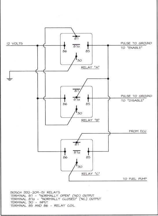
For the circuit to work, you have to splice into the wire that goes from the ECU and to the fuel pump.
If you don't have an alarm, you could use two momentary switches to "enable" and "disable" the circuit. The switches should have ground on one side. Mount the switches in different locations and even if somebody sees you using the switch you use to activate the circuit, they don't know where the other switch is located.
You could use the "disable" switch as a "panic" button if you thought that you were going to get "jacked" (a term that is hard for me to use due to my age).
If you hooked up the circuit to a "switched 12 volts", the circuit would go to "disable" every time that you turn off the car. You would then have to hit the "enable" switch after turning on the ignition.
The circuit does not have to be mounted where the main alarm unit is. This is helpful if the thief thinks that just removing the alarm will help get the car to start.
When the circuit is in "disable" mode, all relays are turned off and as a result, they don't consume any electricity that could drain the battery. When in "enable" mode, only two of the relays are energized.
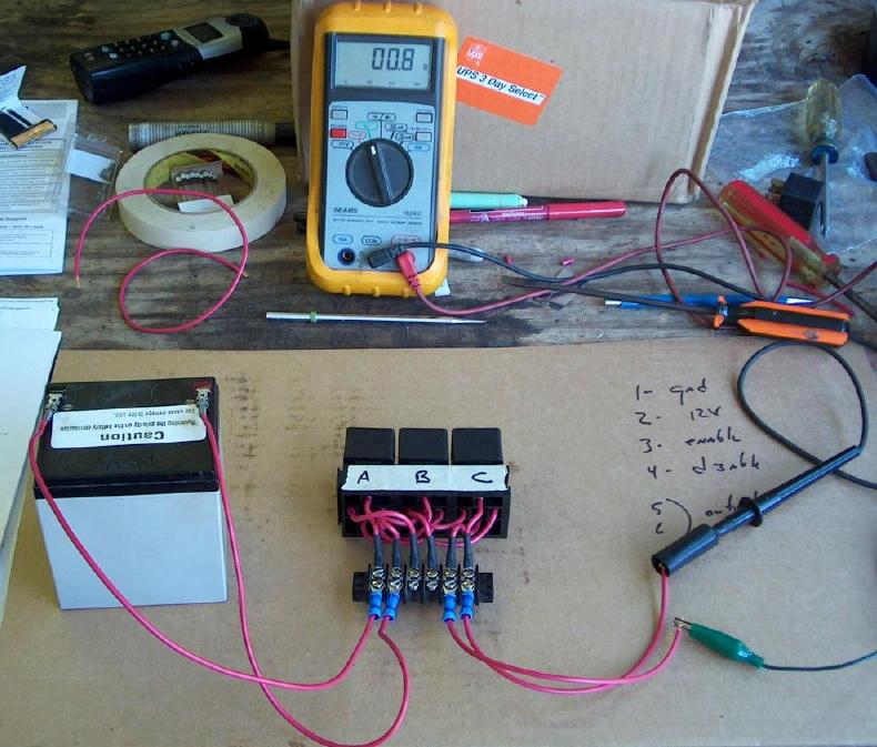
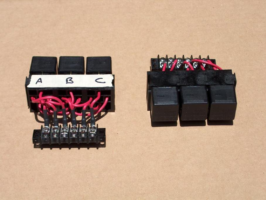
The photo on the right shows two of the circuits that I built up. The relays are plugged into sockets that can be "ganged" as a group and are removable if I have to replace one.
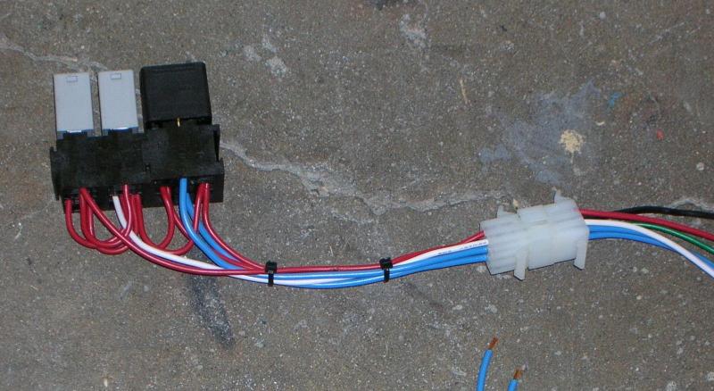
There are two things different about this one, but it functions exactly the same.
The connector is called a Molex connector and they are easy to get from an electronics store (Radio Shack should have them). It can make it easier to hook up and hide.
The other difference is that two of the relays are smaller. Not only are they physically smaller, they also don't handle as much current (they don't have to). I still used the larger relay for the main current line.
Closing comments;
I like using sockets so that it's easy to remove a relay if required. Don't think it's a requirement!!