Installing "URO" Rubber Front
Suspension Bushings (on the cheap)
Originally written; May 25, 2009
To start off;
My car is a long term project and it will be quite some time before it hits the road. It's currently on a chassis jig and I'd like to get it off of it so I can do other items. This means I've got to get it on it's wheels.
I picked up a 911 front suspension for it and for various reasons had to replace the bushings in order to put it all together.
Through out the project, I've tried to not spend money on stuff that will have to be replaced latter. (very limited budget!!)
What I'm getting at is that if I had the money, I may have followed a different path. That's not to say that there is anything wrong with the URO bushings for a street car!
My approach to this project was to show how it could be done for a absolute minimum cost and investment in tools.
This was done on a 911 front suspension and the reader has to keep in mind that the 914 uses a smaller diameter torsion bar. As a result, the diameter of the "guide" tool I used may not work with the 914. Be creative!
To be perfectly blunt;
Elephant Racing sells what appears to be better quality rubber bushings and they come with tools required to install them. The tools are titled as "patent pending".
They will not sell the bushings, minus the "tools" and the price difference was significant enough to warrant using the URO bushings for my situation.
What I made up and used, is for my own personal usage and is not outside of the realm of what any machine shop would do in order to press bushings in place.
Tools and parts needed;
1. Of course you need the bushings. I paid around $45 for them from a local suspension shop.
2. From Home Depot, you need a length of 1 1/2" (id) PVC pipe and coupler. (or ask a plumber friend for a foot of it)
3. From Home Depot, you need a length of 3/4" (id) PVC pipe and a coupler. (this may be 911 specific!) (or ask a plumber friend for a foot of it)
4. From Home Depot, you need two 5/8" bearing plates (in the framing hardware section)
5. From Home Depot, you need a length of 5/8" threaded rod that is about four feet long and three nuts.
6. From Home Depot, you need some JB weld.
7. From a bearing supply shop, you need a 5/8" thrust bearing. It may be possible to do this without one, but I wouldn't recommend it. The bearing I got cost about $12.
8. You should have a level that gives out some form of reading. I found a digital one at Sears, on sale, for around $30. They also have a pendulum style one that is something like $8.
9. You need two wrenches that fit the 5/8" nuts you purchased. (if you don't already have them, you are in sad shape)
Quick notes before starting;
Although this really doesn't take much time, plan on spending a full day at least. And that's assuming that you have the arms already out of the car and parts are clean.
Plan on installing the lower arms in the car before you call it a day. There is a reason and I'll get to that latter.
You should check the angle that both end brackets are at, prior to taking them apart! Write this down somewhere and don't assume both arms will read the same (although they damn well should!!)
Here we go;
You have to remove the original end brackets and the easiest way is to just heat them up with a propane torch until the rubber loosens up. Then just twist them off.
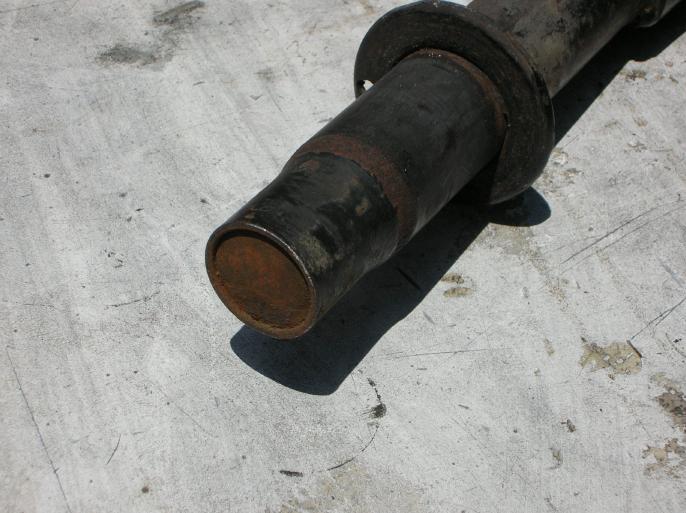
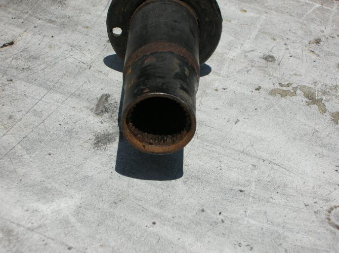
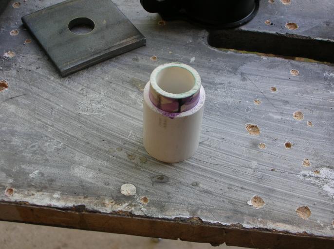
The next step is specific to how I did it (and didn't require a press). You want to remove the torsion bar end cap from the arm.
The photo on the left shows the cap in place and the photo on the right shows it removed. It's just a press in cap and could best be described as similar to a freeze plug. You remove it by installing the torsion bar and giving it a couple taps (on the other end, where it's exposed) with a hammer. On mine, they came out real easy.
Now to fabricate the special pressing tool.
Take the length of 1 1/2" PVC tube and glue on the coupler. It takes a special glue that any plumber would have. (you should let this set for around two hours to fully harden)
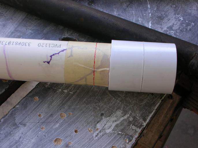
Then figure out how much the tube has to stick out of the coupler. I initially just subtracted the height of the bushing from the bracket, but found this to be wrong. The reason was that I didn't take into account the fact that while pressing everything together, the rubber bushing is forced "wider", taking up more space.
So, that photo on the right isn't really the finished "tool". I ended up with the inner tube extending 0.35 inches from the coupler.
Next are just some general photos.
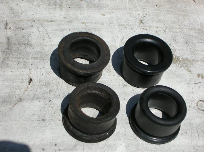
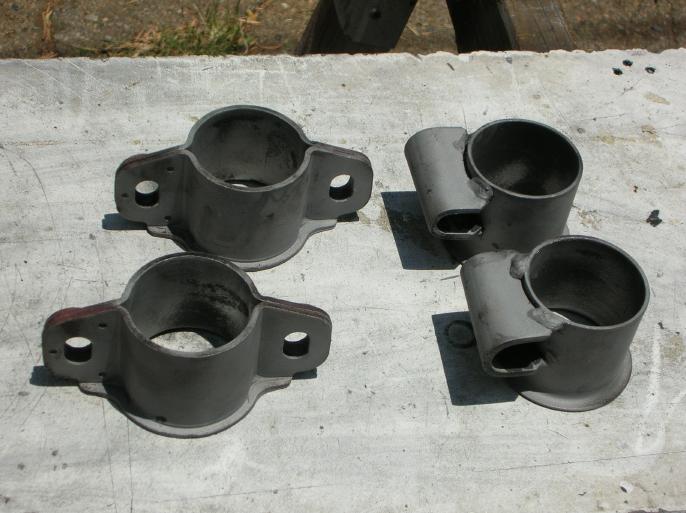
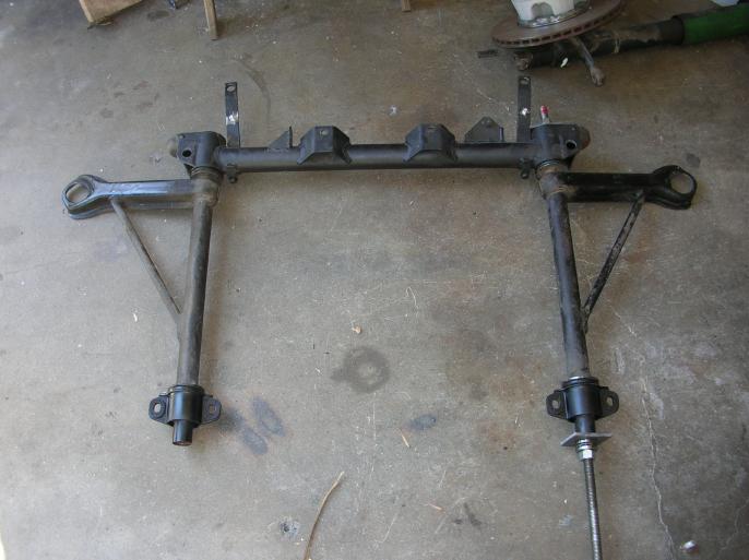
On the left you can see the new bushings and also the old ones. On the right are my brackets after sand blasting them. I'm not sure if this matters, but I painted the outside and inside of the brackets. I really don't know if painting the inside surface helps installing the bushings or not (less friction??).
Note in the photo above, on the right, that the "rear" brackets are not the same! The width of the "U" shaped section is different. When installed, you want the wide section on the top.
What you can't see in the photo above, on the right, is that on the front brackets there is an added metal piece that goes around the bolt hole opening. That should face upward once installed.
So, on the rear bushing brackets there is a "left" and a "right". On the front bushing brackets, there is a "top" and a "bottom", but the fronts are interchangeable.
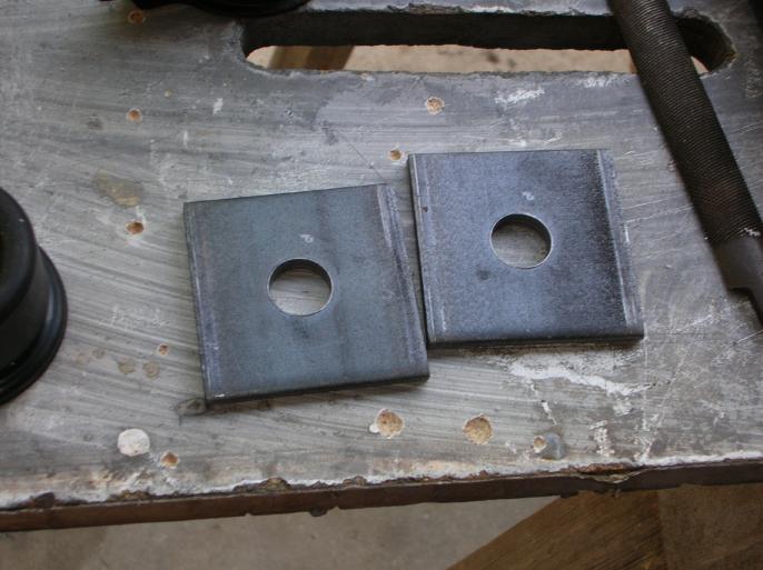
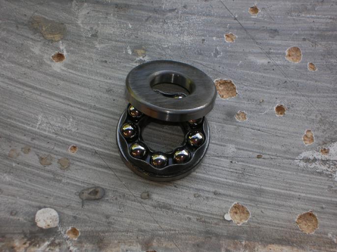
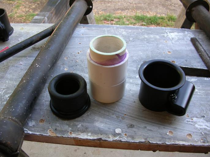
On the left are the 5/8" bearing plates I got from Home Depot. I didn't drill the holes, they come this way.
On the right is the 5/8" trust bearing. This was the biggest cost item at around $12. It may not be required if you grease the nuts real well, but I'd highly recommend using one. The idea is that it helps prevent the bracket and bushing from rotating while installing it.
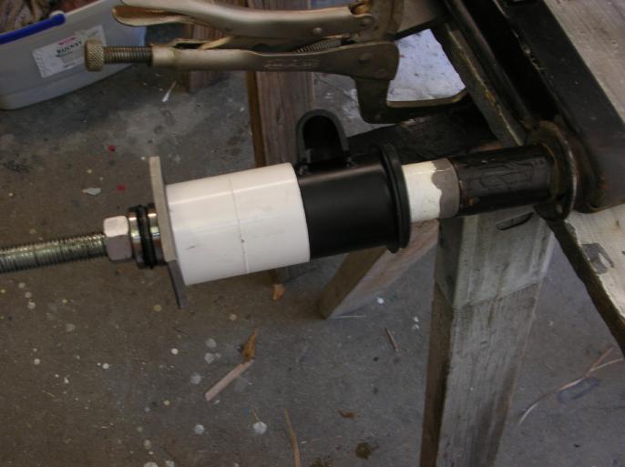
The next photo will give a good idea on what I did.
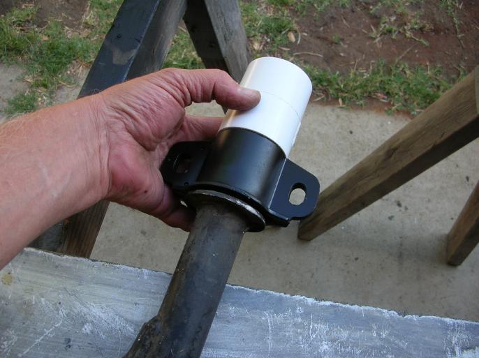
While clamping everything together, the coupler section of the "tool" presses on the metal bracket, while the inner section prevents the bushing from working it's way through the bracket. In other words, without that inner tube section of the tool, you could press the metal bracket clean over the bushing.
Tools in hand, here we go.
It helps to clamp the arm to a work surface and depending on how you are indexing it, it should be horizontal.
Slide the threaded rod though the arm and on the other end put one of the bearing plates. Double nut that end so you can put a wrench on it to prevent the threaded rod from rotating.
Slather the bushing with dish washing soap and push it all the way into the bushing. Ya, I know the bushing is shown in the photo only half way shown. I just found it easier to install it all the way, but don't have photos showing it.
Slather the inside of the bushing and also the arm surface with dish washing soap. I found it dries out pretty quick, so just keep some water handy to re-wet it.
Push the bushing and bracket on the arm and get it's "indexing" close.
Install your special pressing tool.
Install the bearing plate, thrust bearing, and nut.
Now all you have to do is tighten down that nut while holding the double nuts at the other end of the threaded rod.
Piece of cake.
Here is what I did in regards to "indexing" the bracket. Some of this is overkill if you are going to promptly mount the arms.
I clamped the arm to the work surface so that it was horizontal and used the level to verify it.
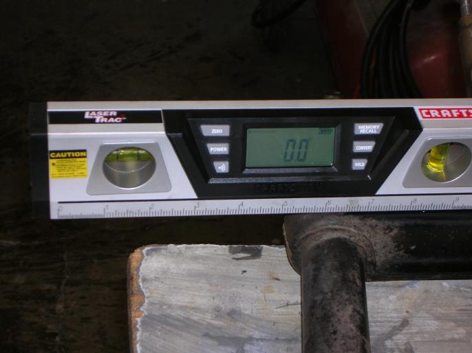
Then I checked, and adjusted, the bracket to the angle I wanted. Don't assume that the angle I chose is correct!
The reason for the bolts and washers through the bracket is so that I can set the level on them. (other than just eye-balling it)
Notice the bearing plate at the other end of the arm assembly.
At the other end (toward the rear of the car) it gets a little more difficult due to there not being a step in the outside diameter of the arm.
So it's back to the PVC solutions.
As I said on the top of this page; I was doing this on a 911 front suspension, which has a larger diameter torsion bar. This solution may not exactly work on a 914 arm.
The object is to have something that the bushing can go over and then taper outward to match the diameter of the arm.
I started by gluing a coupler on the end of a length of 3/4" PVC. I then built up a taper using JB Weld. Pretty straight forward. The tube section only has to go into the arm a minimum amount. It's just to keep it in line.
Once again you want to soap up the bushing and push it into the bracket.
Soap up the inside of the bushing and also the arm, with tapered "tool".
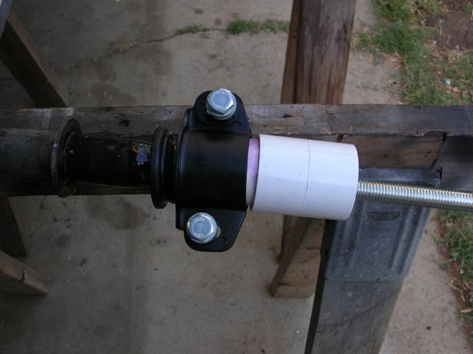
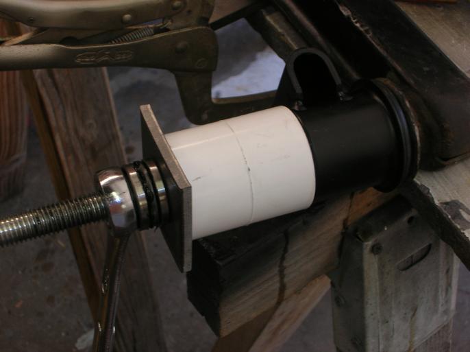
From the left it is; nut, thrust bearing, bearing plate, special pressing tool, bracket with bushing, special tapered tool, and then the arm.
On the other end is a bearing plate with double nuts tightened against one another. (one is hidden by the wrench)
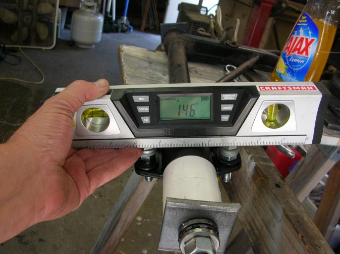
After checking the indexing of the bracket, just tighten it down.
Here it is all tightened down and also checking the indexing.
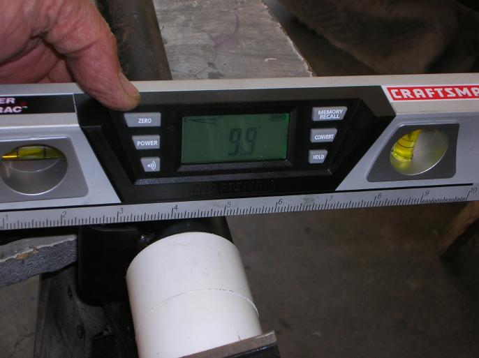
Once again, it's up to you what angle you want to index the bracket at!
Wrapping it up;
The whole process was pretty easy, but did entail some "playing around". Due to not having any form of exact measurement for the "pressing" tools "step depth", I found that on some of the bushings I had to use a straight section of PVC tube to push directly on the bushing to get it to seat as I wanted it. So, just have a section already cut that is about 6" long.
I also found that they want to walk back out slightly and that leads to the next step.
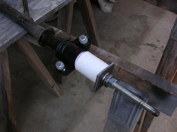
I'm using a steel cross-member (there is a reason) and the fitting of the rear bushing bracket into the cross-member is tight (I don't know if this is an issue with aluminum cross-members). I didn't want to hammer the arms into place, so decided to just use the threaded rod.
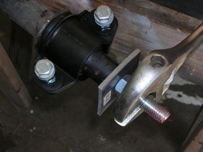
So as shown in the photo above, (on the right hand side of the photo) from the top it's double nuts, bearing place, cross-member, arm, bearing plate, trust bearing, and nut. Tightened down, it went right into place.
I then bolted the assembly to the car.
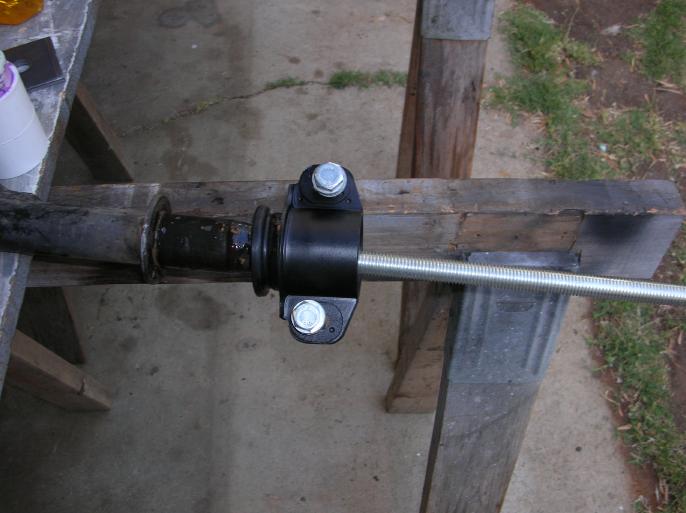
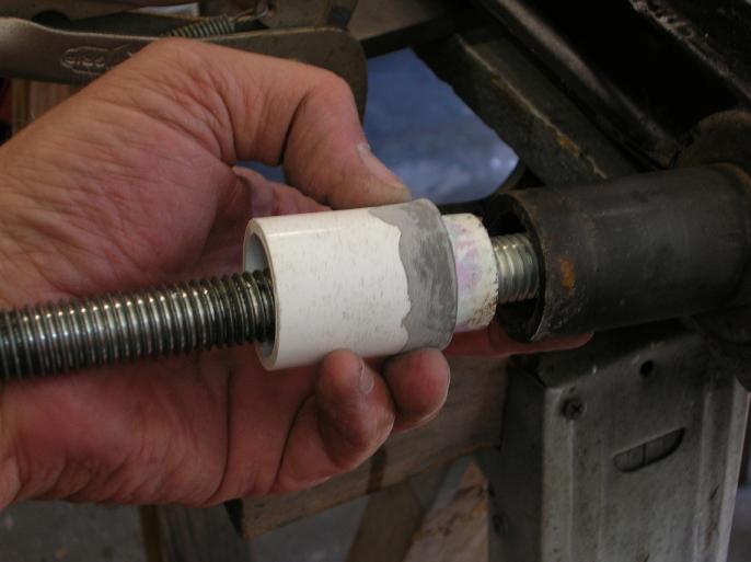
As stated above, the bushings had a tendency to walk around slightly, so I did what is shown in the following photo.
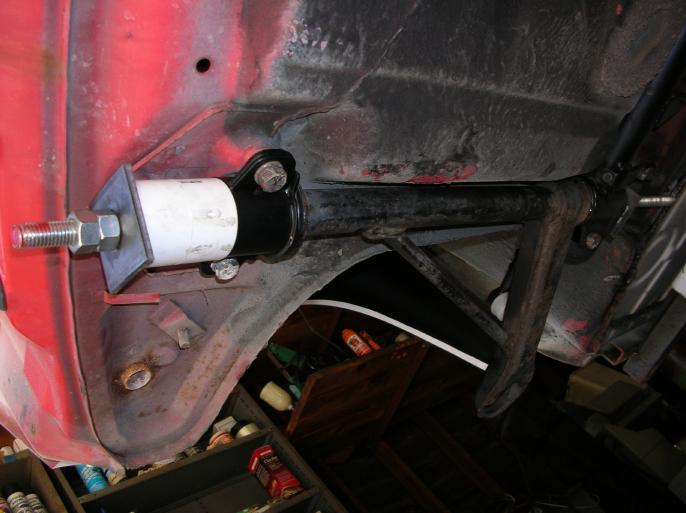
With the cross-member bolted down solid and the two bolts at the front attachment point loose, I installed the tool as shown. By doing this, I could snug everything down until the bushings were properly set and the bolts on the front bracket were in the center of the slotted holes of the front bracket. I then tightened down the bracket and removed the tool. (the trust bearing is on the rear-ward length of the threaded rod)
After cleaning the bore of the arm, I was able to slide the torsion bar in from the front and then hammer back in place the front cap that was removed.
Since I was doing this pretty much in one day, I was able to rotate the arms upward and downward to seat the bushings better (all that indexing goes out the window).
So there you go, dirt cheap.
return to my site's entry page
Wes Vann