Fabricating a Dual Master Cylinder with
Balance Bar System
Originally written; March 28, 2009
To start off ------ Why bother;
I tend to like taking on challenges. Some of them come from some weird area within my head. And this is one of them.
By having a balance bar system with dual master cylinders, you can fine tune your brake system.
I did a lot of searching and although there are pedal assemblies from both Tilton and Wilwood that would work, there were limitations. One is a loss of leg room. Another is having to cut up the floor board to get stuff to fit.
I've got friends in the Street Rod industry and re-locating a master cylinder isn't all that un-common. This includes mounting it parallel to the firewall, under the dash.
So, my mind was off running with the idea of mounting the master cylinder assembly parallel to the steering rack, on the passenger side. It would require canting the master cylinders toward one another to better fit (if this wording isn't clear, look at the following photos to see what I'm talking about).
I used the Tilton web site to find out what size master cylinders I would need.
I picked up the master cylinders and balance bar "kit" from Wilwood. I'd have preferred using the Tilton parts, however the Wilwood ones are half the price.
This write-up shows the process I went through to get the final results. There were several "back-steps" taken. I'm showing the process so that you can figure out if you want to do it the same way, or maybe see a better way. I do have to say I'm real happy with the final configuration.
Was it worth it? It was a great mental challenge and I'd do it again (if I hadn't done it once already).
Worthwhile links
Tilton Engineering;
Wilwood;
Initial master cylinder mounting bracket;
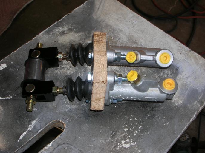
I used a piece of wood to hold the master cylinders at the spacing required for the balance bar. (I think it's something like 2") It holds them at the angles I wanted to get a better fit between the firewall and rack boot.
Once that seemed to fit, I fabricated a steel equivalent.
I then had to "locate" where the pivot point for the balance bar would occur. I figured out the offset from the master cylinders required and distance from the steel bracket. I made up two temporary "towers" that would hold a threaded rod. This indexes the pivot point in space. Then it was a matter of welding in the brackets that form the pivot point.
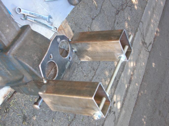
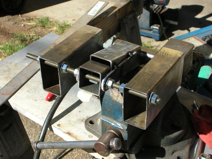
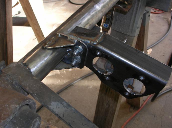
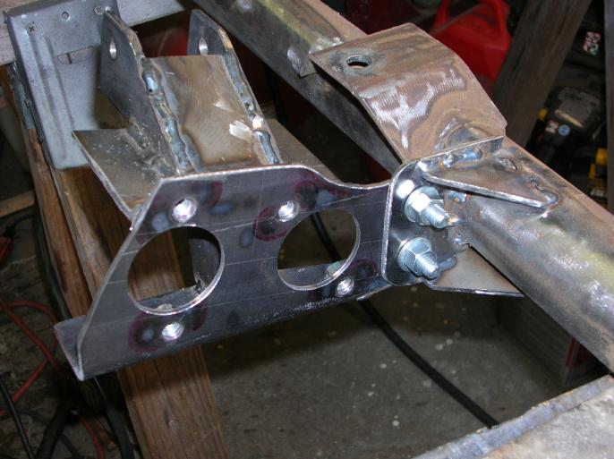
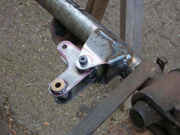
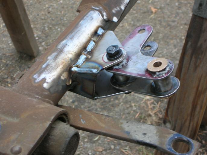
So, here are a couple progress photos of the first generation assembly.
The bell-crank;
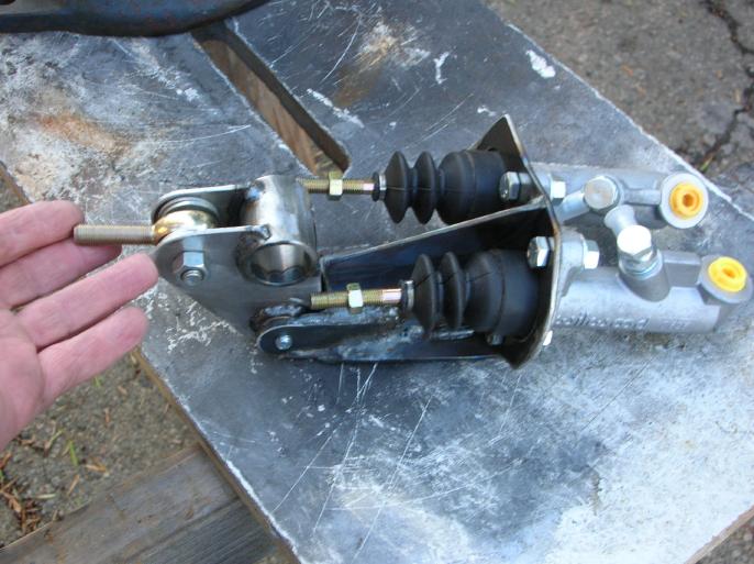
My first thought was that the bell crank part of system would be easy and the following photo was my original intent. It was all wishful thinking and I'm just including it so that you know that the process had a lot of re-thinking required. It's a good photo to more clearly show the concept. It's just a concept mock-up!!
In order to get everything to line up and fit within the confined area, I had to swap around the bell crank. This would result in the two push rods hitting one another. The solution was to have one of the push rods a "tuning fork", where the push rod from the pedal passes through it. This works due to the fact that the bell crank rotates on a fixed shaft.
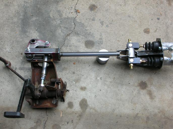
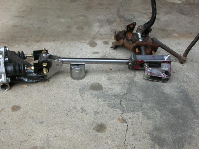
Getting the assembly to fit;
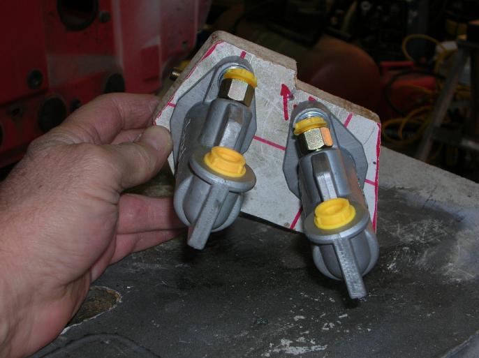
In the following two photos show everything in place. That red plate bolted to the firewall is supporting the pedal push rod in place (centered within the hole in the firewall).
The reason for the c-clamps in the left photo is that I realized that if I install the master cylinder upside down from originally intended, it fit better. So the master cylinders are rotated.
This meant that I'd have to build the second generation master cylinder!!
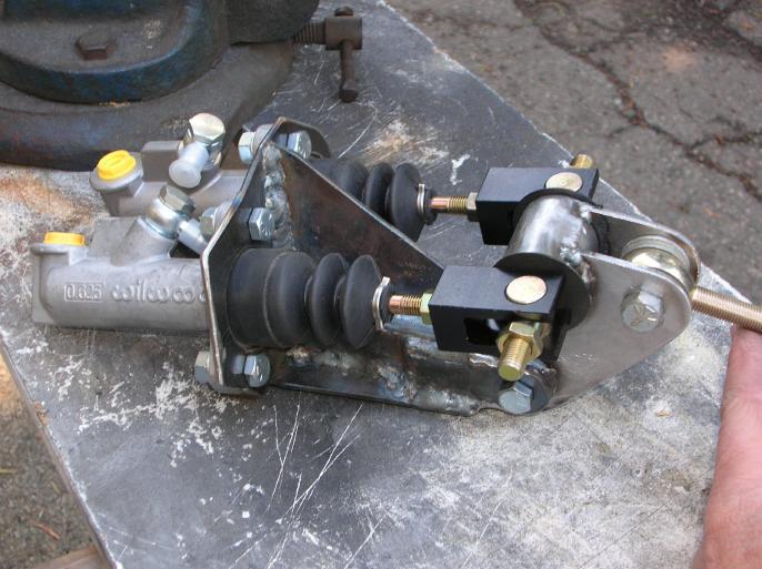
And here is a photo of the final second generation master cylinder bracket.
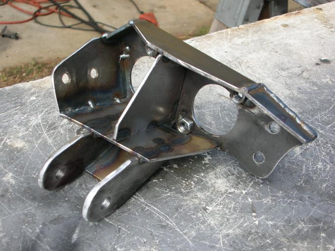
Attachment of the parts;
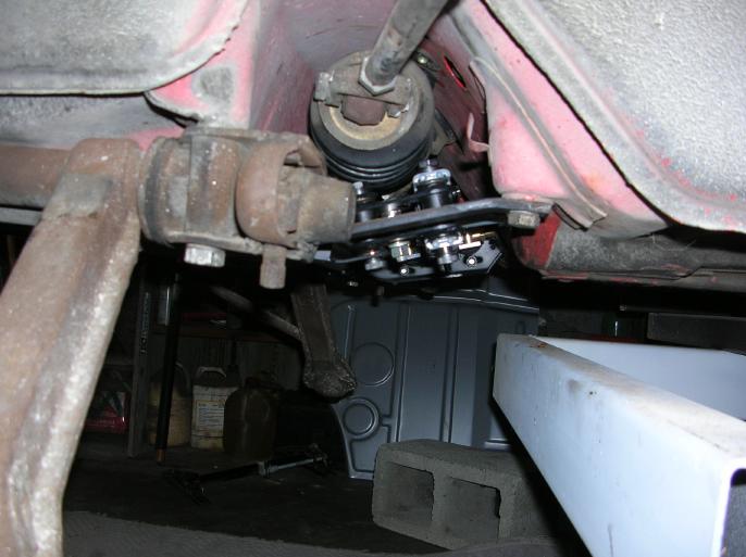
The master cylinder bracket is bolted to a bracket welded to the front suspension cross-bar and also to the floor pan, forward of the steering rack.
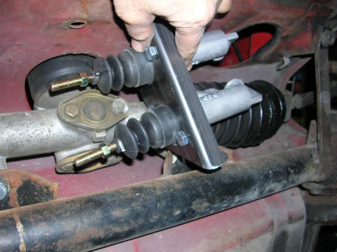
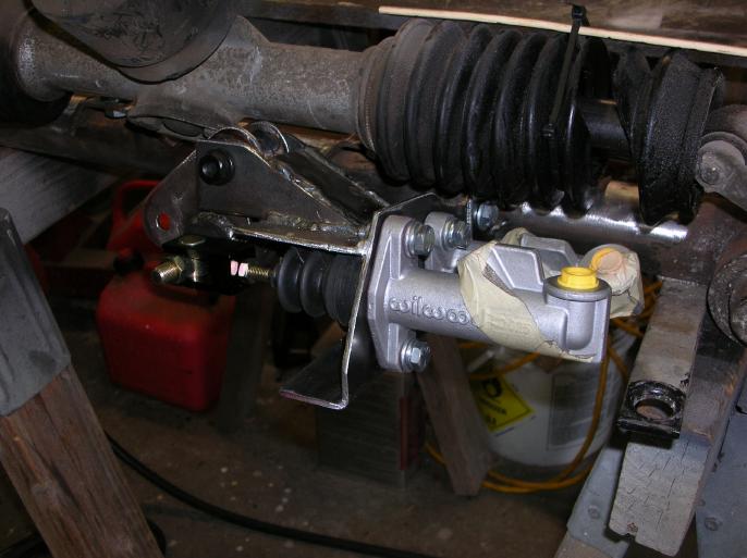
In the following photo, you can see how the master cylinders clear the steering rack boot. (I need to purchase new Lemfordor Turbo Tie Rod end units, which will have new boots. I have hopes somebody will put together a group buy)
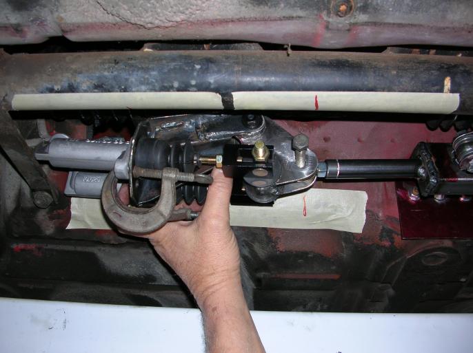
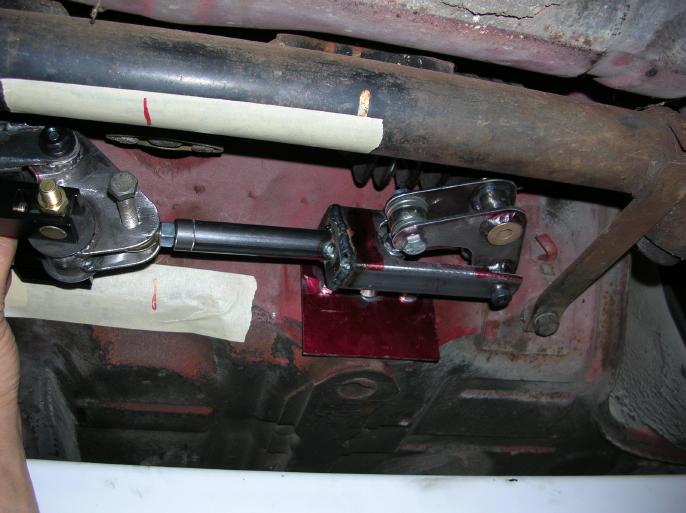
The next two photos show the bracket that holds the bell crank in place. It may be hard to believe, but this is a major critical part in order to everything to work properly! The orientation of the pivot shoulder bolt has to be correct or the pedal push rod will rub on the tuning fork push rod. With everything in place, under the car I had to tack weld everything in place. I then took it all apart and added gusset plates and did final welding.
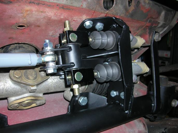
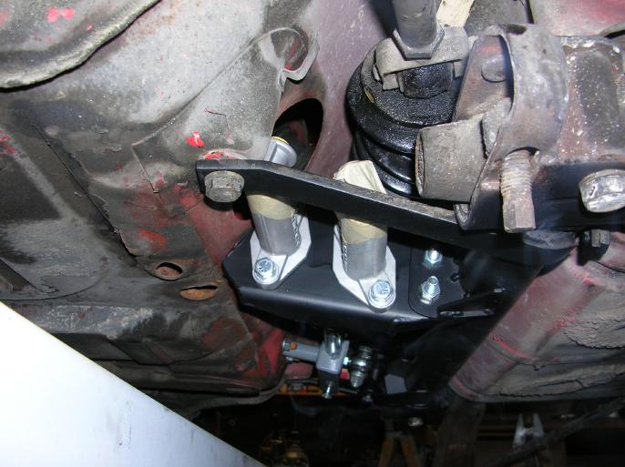
Finished Photos;
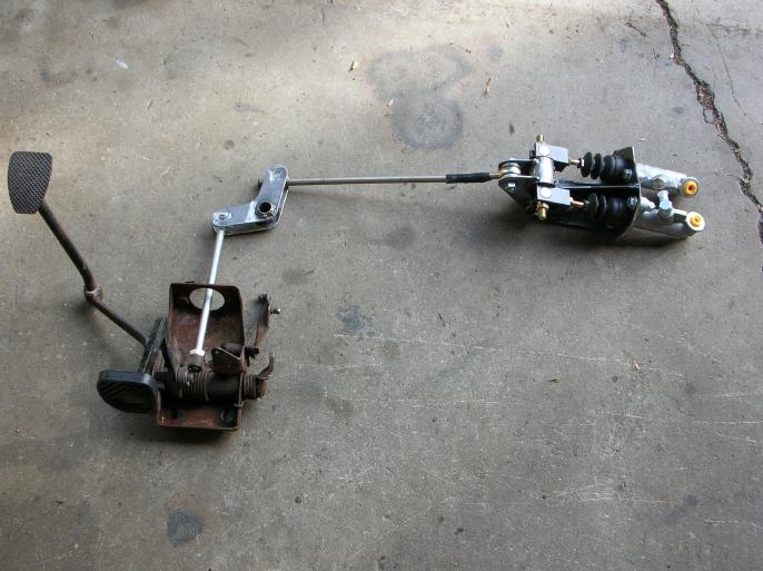
Here are four photos showing everything in place. It all works smoothly and from within the drivers compartment, you have no idea of what's going on.
I don't have the master cylinders hooked up yet. The fact that I don't have front brakes yet is a good reason.
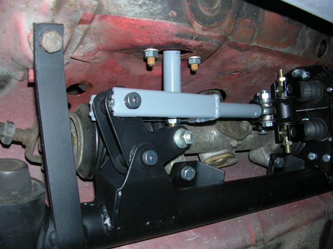
A couple photos that help explain what I've done and how it works;
I used shoulder bolts for the fixed pivot points.
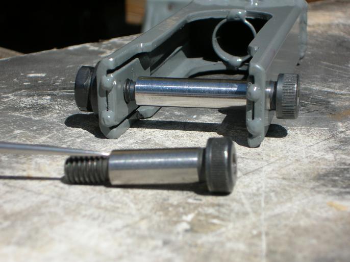
The bell cranks have bronze bushings that are graphite impregmented. They rotate on the shoulder bolt shafts.
Now a key thing about the shoulder bolts is that they tighten down on the shoulder on the left. The holes through the brackes (tuning fork) are different sizes. By doing this, I don't cinch down on the bell crank. (that upper bolt isn't tightened down)
In the next photo I'm showing what compromises a "balance bar" system.
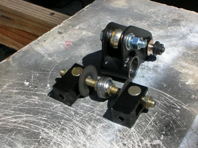
By rotating the threaded rod / shaft that's between the two clevis', that spherical bearing can be moved from side to side. By doing this, you can vary the amount of force going to each clevis.
So there you go.
return to my site's entry page
Wes Vann