The Work Platform
Last up-date; March 12, 2008
To start off;
The design of the platform was taken from what Jeff Hail did. I changed a couple things about it, but it's pretty much the same. That answers the issue of plagiarism. The biggest difference is that I rotated the lower tube so that it was up-right.
Jeff Hail's "bringing out the dead" This page covers Jeff's reconstruction of a 914 and is where I got the ideas and information on how to build the platform.
Some people will state that a "rotisserie" is the thing to do, but if you have to remove major sections they don't give the support required. I wanted something strong and straight that I could work off of. The points supporting the car can be moved as required or more added
Building it
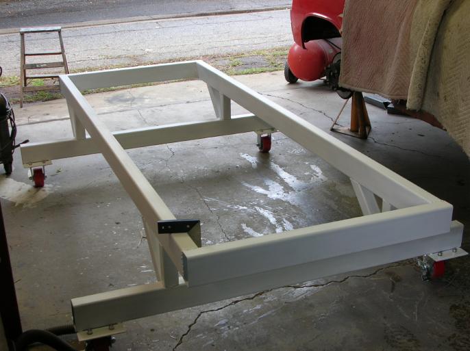
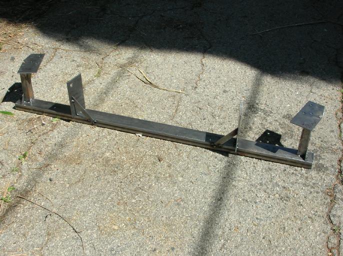
It's best to first post up a photo of the basic platform.
The rectangular tubes are 2x4x1/8". The square tubes are 2x2x1/8".
The long top tubes are 8 foot long. The short top tubes are 3 foot long. The outrigger tubes are 5 foot long. The up-rights are 6" tall. The casters are 5" and that makes the mounting flange 6" above the slab.
The reason for the length of the platform was so that it could run from behind the front suspension, to the rear where I could add a support to the rear transmission mount.
The reason for the width is so that it still clears the rear suspension (the attachment of the shock to trailing arm).
The reason for the 6" tall up-rights is so that there is enough room for me to crawl under the framework.
The reason for the out-rigger being 5' is so that it provides as much stability as possible and still falls (slightly) within the width of the car.
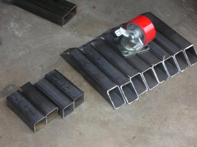
I paid about $50 for the casters and about $220 for the steel. I had two 20 foot lengths of 2x4x1/8" and one 20 foot length of 2x2x1/8" steel delivered and went at them with the cut-off saw.
On the ends of the long top members, I welded on a length of angle that when rotated over, would provide a seat for the short top members. (this is prior to spot welding) This gets removed once not needed so you can weld around the full perimeter of the tube.
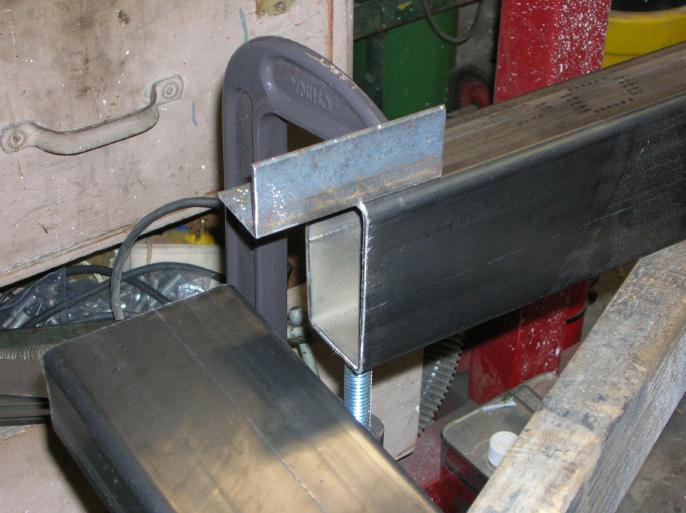
Then I positioned the top members on saw horses. The saw horses support the long members, and the short members are sitting on the angles with C clamps holding them in position.
To make it "square", you have to measure from one corner to the one diagonally across from it. That measurement has to match the distance measured from the other corners.
Now the object of the following is to have a flat and true working surface. This is critical!! Now most garage floors have a slope for drainage, so you can't really just build the frame on the floor and expect it to come out true. By "true" I mean that the top surface is in a constant plane, without twist. It really doesn't matter if when you are all done, it's not level.
What I decided to do is use a contractors laser level to align everything. In the following photo, the laser level is sitting in the middle of the main frame. (the arrow is pointing at the level) Now this kind of tools costs a lot, but you can rent them and it took only about a half hour to use it.
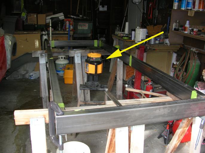
Now a laser level is way cool!! You set it on just about anything and turn it on. It takes a while to self level and then spits out a red laser light a full 360 degrees around it. I set the height so that the projected light hit the inside of the frame (on the high side).
At the high corner, I took a small framing square, put masking tape on it, and then marked where the laser light hit it. (I'm cheating with the next photo due to it's having been taken out of sequence)
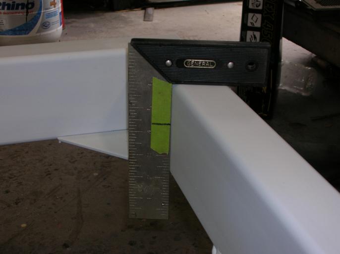
Then take the square to each of the other three corners and shim up the corner until the laser light hits your reference line. You will have to do this a couple times due to the fact that when you shim one support, it throws off some of the others.
No measuring required, just a mark on masking tape and a 5 grand laser level. (by the way, I couldn't get the red laser light to show up in a photo)
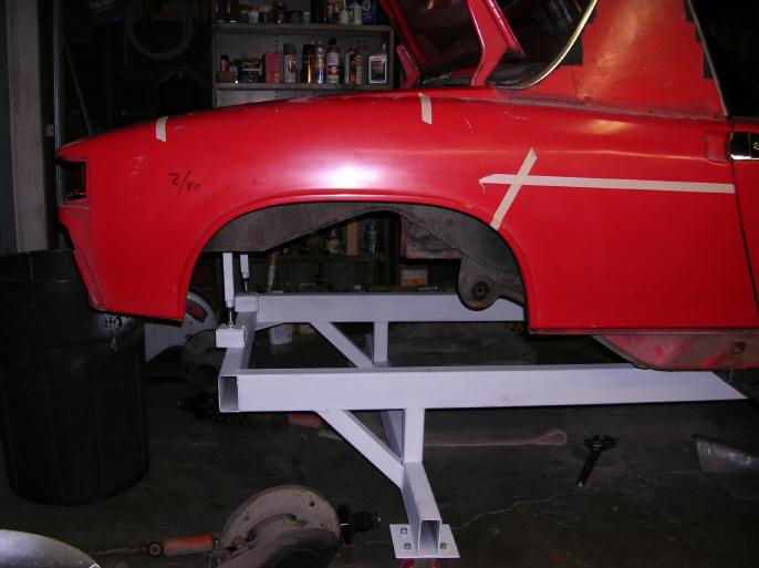
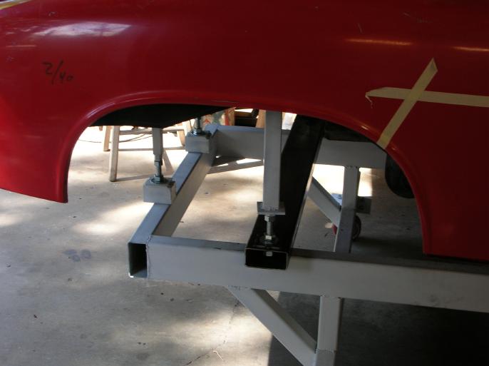
The main frame was welded up and then all the other items welded on. It's pretty straight forward, just look at the photos. I painted it up flat white so I could mark on it if required. You have to make sure that all four of the 6" uprights are the same! (grind the longer ones to match the shortest one) Here is that first photo again;
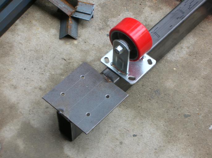
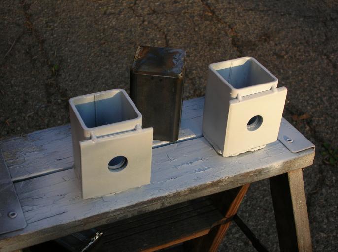
Next up was how to support the body (minus engine and transmission) on the platform. I decided to use 5 foot long sections of 2x2x1/8" tube and also 8" long sections of thick wall square tube with a groove cut in it.
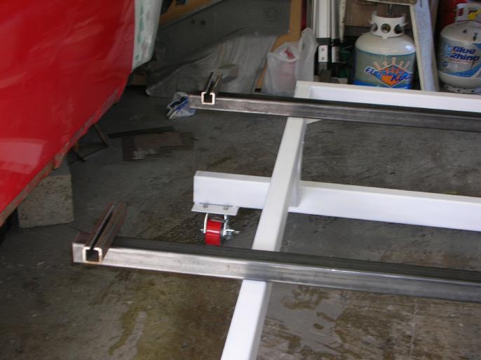
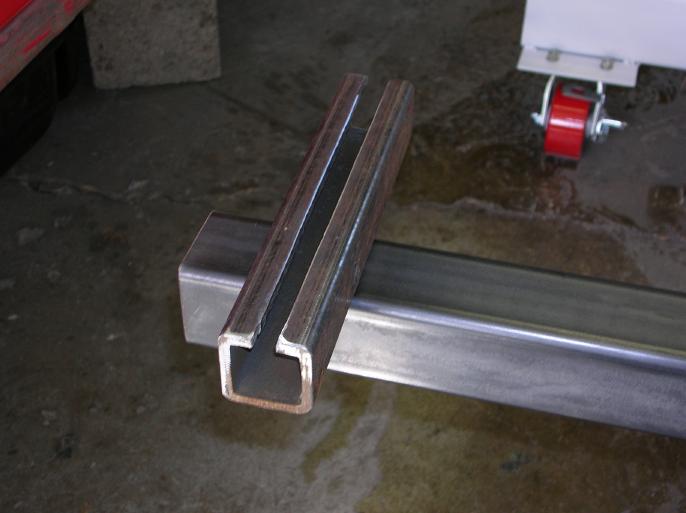
The reason for the groove is to clear the pinch weld section of the frame rail.
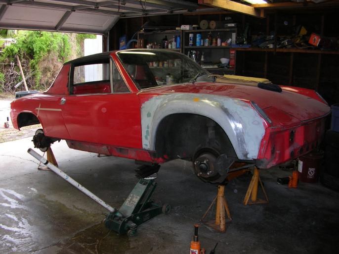
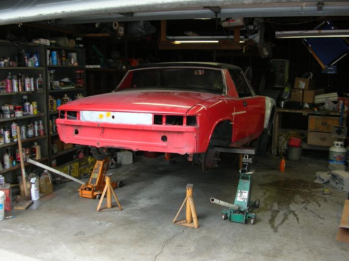
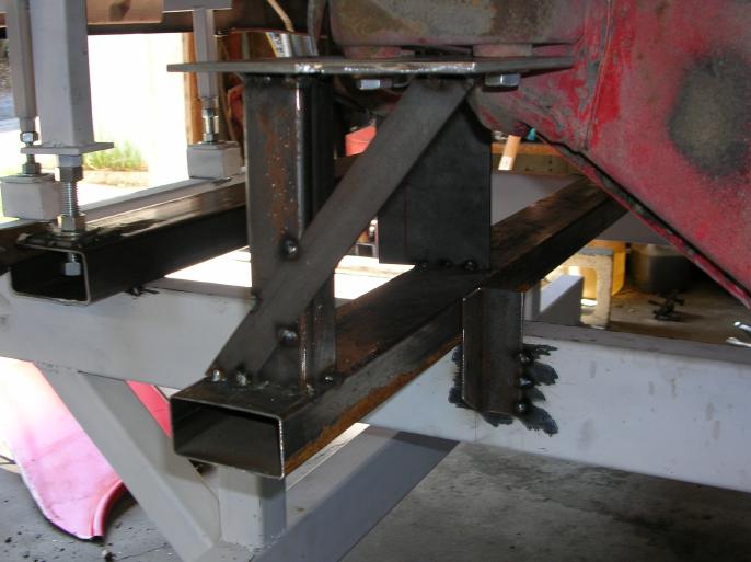
Now the fun starts! I had to raise the car so that I could slide the platform under it. The first photo shows the front raised up as high as possible and sitting on jack stands. In the other photo, the rear has been raised using a 7 foot length of tube steel and two floor jacks (those jack stands are just sitting there, when the photo was taken)
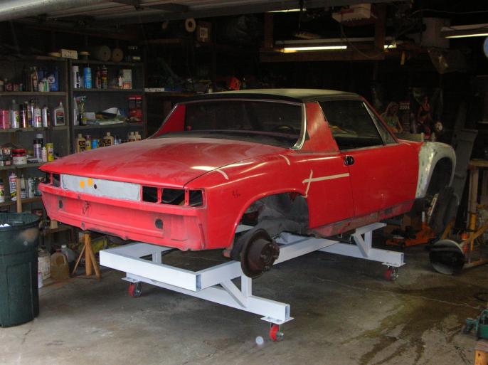
At this point, I could roll the platform under the car and then lower it.
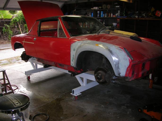
Here is the car sitting on the platform.
Now that finishes it up for tonight.
I've got to make up supports that attach to the rear transmission mounts and also ones that go to the rear shock attachment points (after removing the rear suspension). I also want to tack weld the out-riggers.
March 4, 2008;
I built up the support struts that attach to the rear transmission mounts and also ones that attach to the rear shock mount.
Following is the struts that attach to the rear transmission mounts.
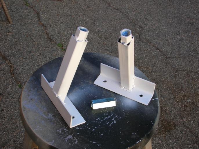
The square tube is 1" square and the angle is something like 2" by 2". I did slight grinding on a 5/8" threaded couple (long nut), slid it into the end of the square tube, and welded it in place.
The two box's are for bearing on the main frame. The square plate is a standard (home) construction BP5/8 bearing plate available at home depot (go to the Simpson hardware section).
All of the threaded rod shown is 5/8" diameter.
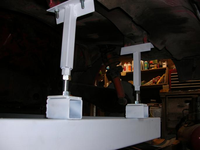
Here are the struts installed.
At this point, I pulled out the rear suspension.
Now for the shock mount strut.
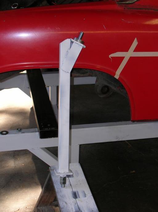
This is the shock support strut.
At the top there is a 5/8" bolt with it's head welded to the square plate (BP5/8) that is at about a 10 degree angle. There are four washers at the top in order to help clear stuff within the body cavity. The whole idea of this is that the strut tube goes straight downward.
On the bottom is another of those BP5/8 square plates and there is a nut welded to it. The threaded rod can go into the square tube.
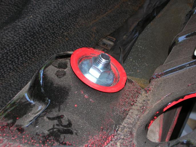
Here is a photo showing the strut bolted to the shock attachment point. The washer is a standard large diameter (not fender washer) washer and it fits well within the pocket where the rubber bushing normally would be.
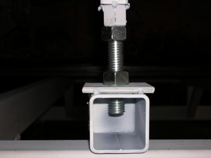
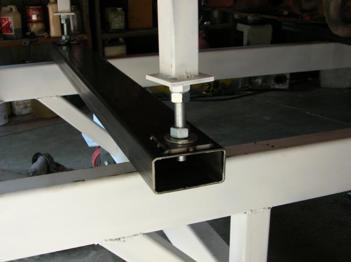
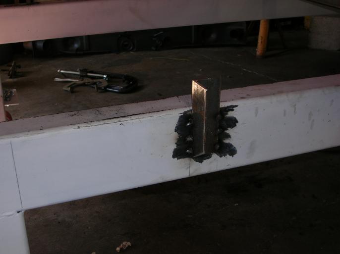
The next photo shows the bottom of the strut and also the cross-beam. Tack welded to the cross-beam is another of those damn BP5/8 plates.
Here is the final photo showing all of the rear supports.
By screwing down any of the lower nuts, at any of the four points, I can raise that point.
What is funny is that the chassis appears to be still fairly stiff and if I screw one point, the others lift off of their support point. That's a real good sign!!
Platform work continues, the suspension jig;
Due to the rust repair work that has to be done to the diagonal section of the longitudinal (box frame section), I've got to remove the suspension brackets. Putting them back on in the correct location requires that I make up a jig. I wanted to be able to remove the jig while working on the car.
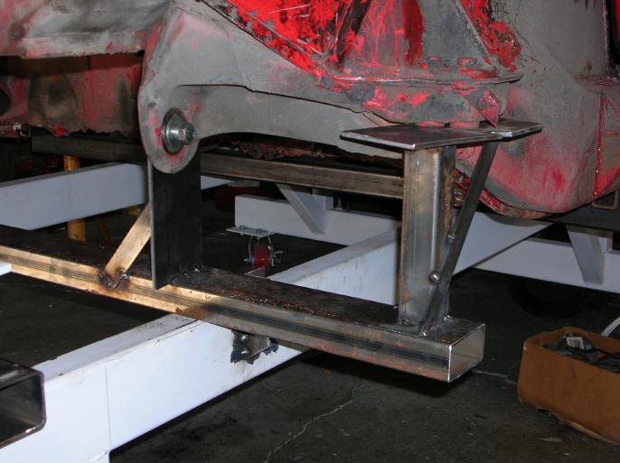
I started out by welding an angle on the platform that the jig cross-member would be C-clamped tight to (along with another C-clamp clamping the jig cross-member down onto the platform). In all of the photos, I've removed the C-clamps, so that the photos are more clear.
The reason for the angle cut at the bottom of the angle is to make it more safe. I know that at some point, I'm going to bash my bald head on it!
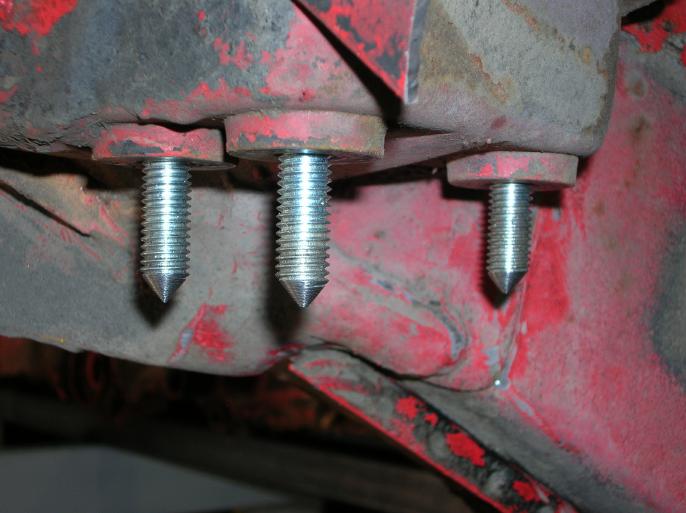
I got a couple bolts that would go into the chassis where the trailing arm (camber shim location) attaches. I cut off the heads and turned them on a lath so that they came to a point.
Here is the process that I did to drill the holes in the plate that attaches here;
First off, just drill one hole. Use one of the studs to hold the plate and use one of the other studs to mark where the next hole will go. Drill that next hole.
Then using two studs to locate the plate, use the third stud to mark the next hole. Drill the hole.
My feeling is that this process will give you the most accurately located holes possible. A lot more accurate than trying to take measurements and transferring it to the metal plate.
The next two photos show the completed jig in place. Once again, the C-clamps have been removed.
At the inner suspension point, there are three washers between the chassis and jig plate. This is done due to the recessed section of the chassis attachment point. The bolts here are metric, ensuring a tight fit.
It's a subtle point, but the reason for the jig plate at the inner attachment being on the inside, is so that the jig can be moved toward the rear of the car during removal. If I put it on the other side, I could then only move the jig forward, due to the angle of the attachment points.
Here is the jig, removed and ready to be put in a safe place!
So there you go.
Wes Vann