Rebuilding the Steering Rack
and Installing "Turbo" Tie Rod Ends
Written; May 14, 2009
To start off;
My car is a 75 914 and I purchased a 79 911 SC front end. When I refer to any of the 911 parts, it's in reference to the 79 that I've got. Other 911 parts may be different!
The reason I got into the "rebuilding" process was that while "bench" testing the two racks, the 911 one felt better. However the mounting threads on the body of the 911 were not good.
So, I started this with the idea of taking the 911 internals and installing them in the 914 housing.
Once both racks were apart and I could inspect the parts, the opposite of what I expected was true. The 914 internals were in better shape. I ended up not using anything off of the 911 rack.
As for why I was installing the "turbo" tie rod kit; once you see the difference in how they attach at the end of the rack bar, it's a total no-brainer!
The word on the net is that you want to get the "Lemforder" kit due to quality issues on units from other manufacturers. I got my kit from Pelican Parts.
I ordered the Weltmeister steering rack offset kit that raises the rack. This lead to other things that I'll talk about latter.
Before you do any dis-assembly, hold the rack arms straight out and measure the distance from ball joint to ball joint. Write this number down somewhere.
There is a very similar write-up on the Pelican Parts web site and that's where I got a good amount of information. Click here to see the Pelican Write-Up.
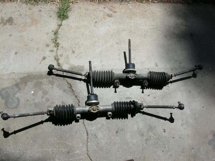
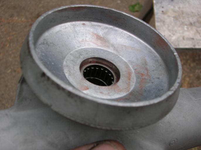
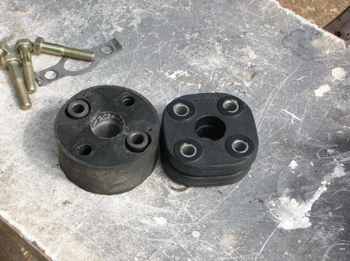
Little facts about the racks (at least in regards to the ones I had);
The 911 rack is on the top of the photo.
Both racks have the same ratio. Both rack bars have the same tooth spacing and both of the pinion shafts have the same tooth count.
The 914 rack bar is 4 1/2mm longer than the 911 rack bar!
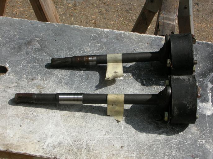
The steering shaft that is attached to the rack assembly is different between the 911 and 914's. The 914 one is longer. This has to be swapped if you want to use a 911 rack in a 914.
Taking it apart;
Remove the steering shaft from the rack assembly by bending the lock tabs flat and just un-bolt it. (I didn't take a photo)
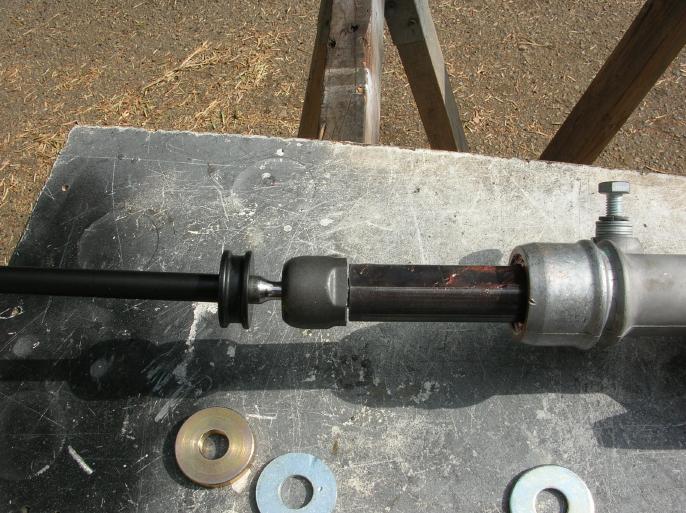
Remove the through-bolt and the rubber bushing that is at the end of the rack bar. (just outside the bellows) Then remove that end of the assembly.
Pry the retainer springs from the two ends of the bellows and then remove the bellows.
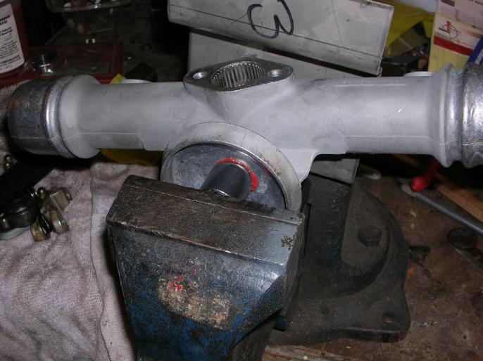
Put the end of the rack bar in a vice and use a drift punch to remove the end piece that's at the end of the rack bar.
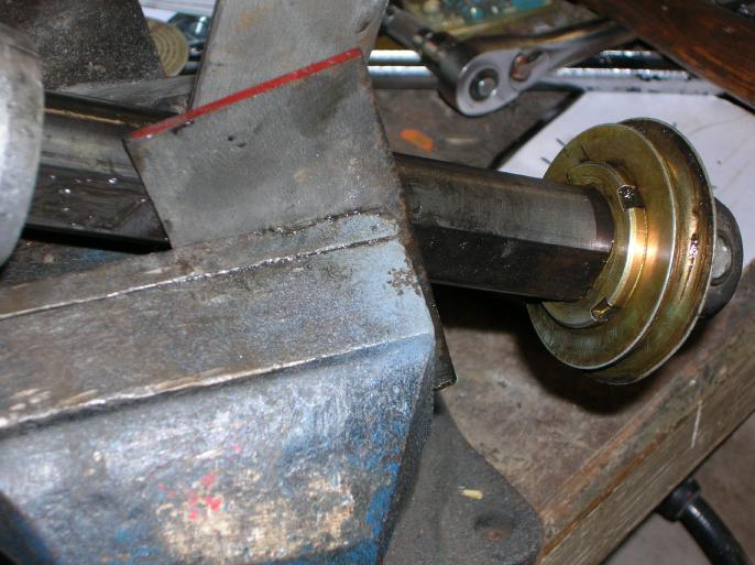
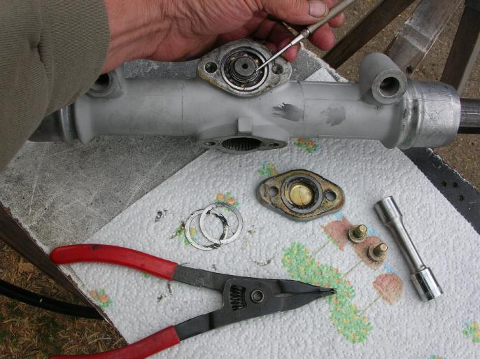
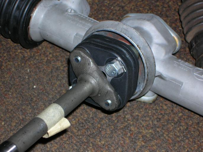
Now you want to remove the nut that holds the flange that the steering shaft is attached. As shown, I used a wrench to hold the flange while a socket could still reach the nut.
Once the flange is pulled off, you get the following parts;
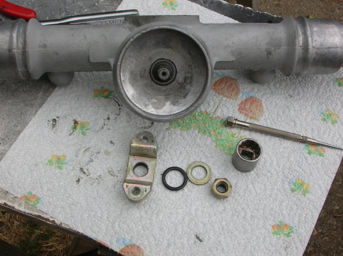
From the left to the right there is the flange, an O-ring, a washer, and the nylock nut.
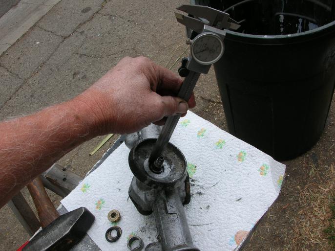
Now this is important!! If you plan on moving or replacing the roller bearing in this location, you want to measure it's depth below the body of the housing. In my case, the depth is 0.15". This depth is the pocket that the O-ring sits in!!! If you don't put the bearing at the correct depth (and it would be easy), the O-ring will not fit correctly.
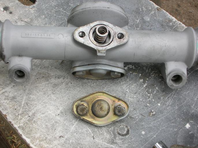
Remove the two bolts that hold this plate in place. What you will find are a couple shims, a spring, and a "cup" that presses against the rack bar.
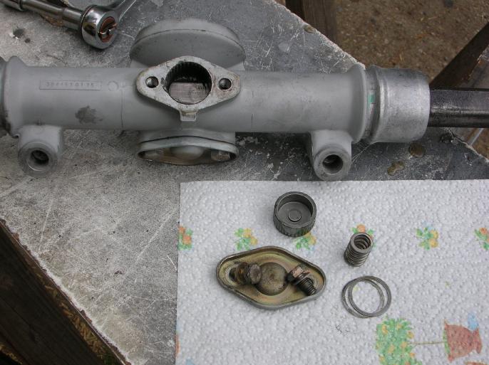
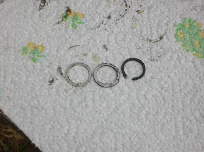
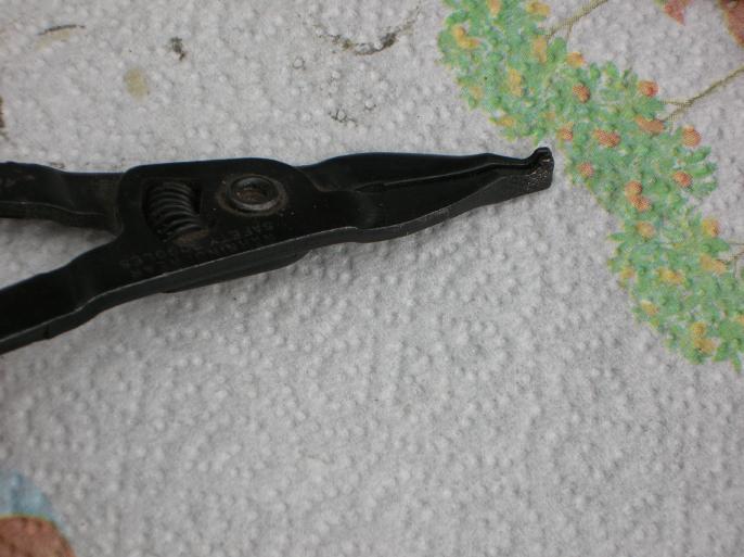
Remove the other cover plate and you will find more shims and also that there is a circlip holding the pinion shaft in place. (that's what I'm pointing at with the scribe) The tool shown is one I got at Sears and it's used to remove that clip.
Once you remove that clip, you will find even more shims. Here is a photo of the clip and also the shims that were between it and the bearing inner race.
And here is a better shot of that Sears tool;
Now you can tap out the pinion shaft.
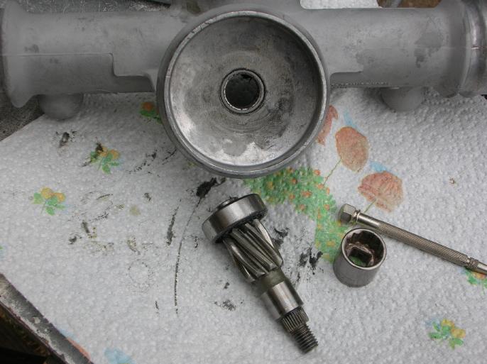
Remove the bearing from the pinion shaft and also the roller bearing from the aluminum housing. That original roller bearing has 26 rollers and they are held in place only by the grease that's still there.
Pull out the rack bar (if it hasn't fallen out all ready).
Clean everything and get out all the caked on old grease.
Now it's time to buy stuff;
The bearings are "industry standard" stuff. The roller bearing is part number 1712. The ball bearing is part number 6202. I went to my local bearing supply shop with the part numbers and the bearings. It seems that the 1712 bearing is no longer available with loose rollers. The one I got had a cage that holds the rollers in place (it's still the same part number, just a different version). The 6202 bearing I had grease seals, which I had the supplier remove so I could lube it better (not really required).
I got the steering coupler lock tabs from Pelican Parts. You need two.
I got the Weltmeister steering rack spacers from Pelican Parts.
I also got the Lemforder "turbo" tie rod kit from Pelican.
As for lube, I found a shop near me that sells Redline and I picked up "CV2" lube. I can't really justify why I chose that product, however there didn't seem to be any other consistant recommendations.
As for the steering coupler (rubber bisket), I picked up two early VW ones and I'll talk about that latter.
Putting the rack back together;
First off, I'd like to talk about all those shims that were removed and set to the side. I cut a corner here and just re-installed them in the original positions. If you were doing this as a (quality) business you would pull out the factory manual and it would show how you are to use a depth micrometer to measure for the required thickness. You would then go to your selection of shims and pick out the correct ones. I don't feel guilty for not doing this because I feel the "tolerance" they are trying to adjust for is in the machining of the rack housing, not in-accuracies in the bearings.
Now before you press in the roller bearing, look inside the bore where it will go and note that there is not a shoulder to prevent it from being pushed in too far! This is why I had you measure the depth before removing the old one.
Notice in the following photo how the side surface of the bearing is below the surface of the housing.
It's within that area that the o-ring will sit.
I just used a socket and vice to press the bearing into it's required depth. (that red stuff is the Redline CV2 lube)
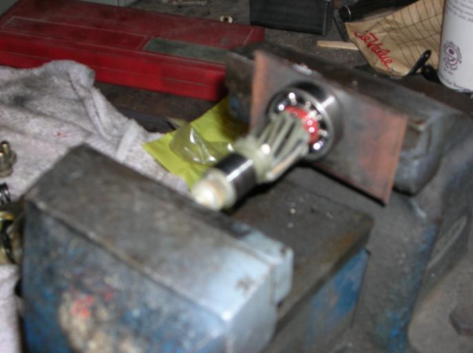
Press the roller bearing on the pinion shaft. (sorry about the focus)
Lube the heck out of everything and slid the rack bar in place.
Work lube into the roller bearing and also the ball bearing.
Then just drop the pinion shaft and bearing into place.
Replace the shims and circlip that is in contact with the inner race.
Put the shims in place (that touch the outer race) and then bolt down the cover plate. (I used a small amount of silicon sealer)
The other cover plate and it's piston, shims, and spring are just a simple re-install after slathering it well with lube.
The same is true with re-installing the flange that is bolted to the pinion shaft. There is one thing that has to be discussed however and I didn't take a photo of it.
Before placing that flange that the steering coupler is attached to on the splines of the pinion shaft, you want to center the rack bar. Just measure how far each end sticks out and match them up. With the rack centered, you want to place the flange on the shaft so that it is in an up and down orientation. This is shown in the factory manual, but I didn't want to "steal" their property and post it here.
When you replace the o-ring, all those comments about the depth of the roller bearing will make sense. (ya, I messed up on the original assembly and that's how I know this. The depth measurement was taken off of the other rack)
Installing the "turbo" tie rod kit;
Installing the tie rod kit is straight forward, but here are a couple things I observed.
In the above photo, you will see the zinc plated thick washer that comes with the kit. The other washers are just standard thickness washers.
I screwed the rod end all the way into the rack bar and it bottomed out! If you didn't have a washer, this could lead to serious problems.
Here is a close up photo;
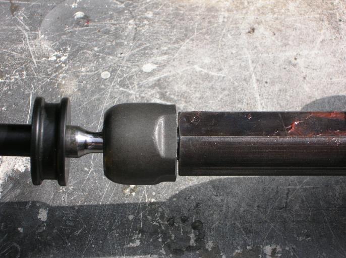
I was checking this due to having read stuff on the net about people not using the washer that should come with the kit.
I then put both sides on the rack, with the thick washers, and measured from ball joint to ball joint. (ball joints screwed in all the way) This measurement was almost exactly the same as what I originally measured before taking everything apart.
So, to ensure I had enough adjustment latter, I chose to not use the thick washers that came with the kit, but just standard thickness washers.
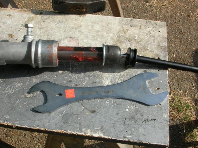
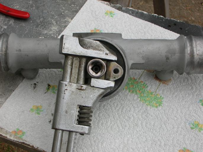
Now to tighten down the rod end, you need a special wrench. What was funny was that I already had one in the tool box from working on bicycles.
The wrench is called a cone wrench and it was made by "wrench force". One side is 32mm and the other is 36mm. The price tag (still on it) says that I paid $22.00 for it, but I don't even remember how long ago I picked it up. Any bike shop can order this wrench for you.
At this point you can put on the new bellows that came with the kit.
The bellows for the "turbo" kit are different than the original ones. On the original ones, the holes at the end are the same. On the turbo bellows, one side is smaller in diameter.
It's no big thing, but there were no retaining springs for the bellows, like there are on the originals. I called up Pelican Parts because I thought they should have been included. Well, they are not needed or even called out in the factory parts diagram. I did however install them on the end of the bellows that is in contact with the rack housing. (overkill?) The outside fits snugly as it is. (as designed)
What about that steering coupler rubber bushing?
Due to using rack spacers, which move the steering rack upward, I wanted to install a shorter "steering coupler bushing". After doing the math, you want a bushing that is about 1" in height.
Now there are a couple ways to handle this, but I'm just too tired from typing to go into the other options. (some of the ideas just be better than what I did)
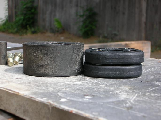
What I came up with was to buy two early VW bushings and stack them.
Here are photos of the stock coupler sitting next to the two VW ones.
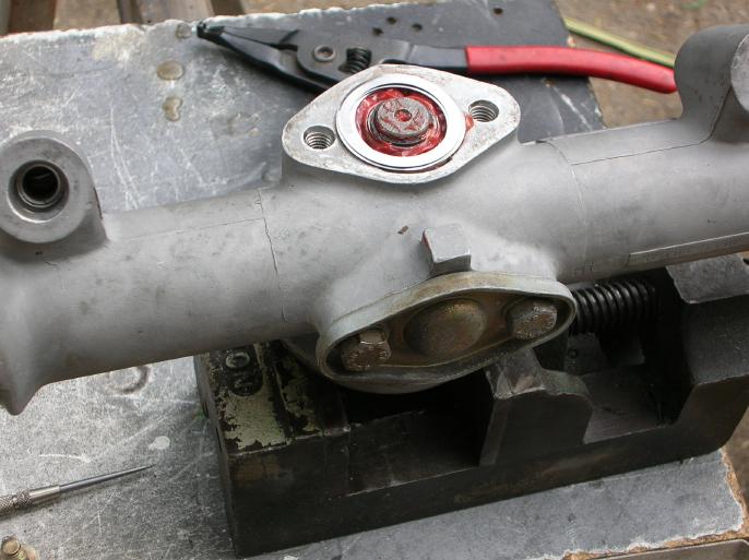
And the following two photos show it mocked up on the rack. (I didn't have the lock tabs at the time and I also bought new bolts that were about 5mm shorter)
So there you go.
return to my site's entry page
Wes Vann