Custom Adjustable Upper Control Arms
Originally written; July 25, 2004
To start off;
I'm posting this information as "food for thought"!
Using these arms may (and you have to assume that they will) cause clearance problems that will have to be addressed for proper suspension travel! Don't try this modification if you are not a qualified welder (or at least know when to take it to one). I bear NO responsibility for unsafe modifications done by others.
Most of the photos can be clicked to see a full screen version. Use your "back" button to return here.
Nobody makes an adjustable arm for EF civics.
There are adjusters that can be installed at the rubber bushings that allow for camber adjustment and these may be the best solution (in my mind), but they can pose a problem with clearance. It's the same problem that you will have with arms like what I fabricated and it has to deal with the contour of the inner fender. (The solution is to notch the upper framework) Another issue with some is that they are difficult to adjust if you want to play with your camber settings at the track (road race guys)
Another solution is the adjustable ball joint. This is a ball joint assembly that is slotted. The problem (once again, it's my "opinion") is that this moves the arm upward and that again causes clearance problems with a lowered car. (The solution once again would be to notch the upper framework, but the notch would have to be even "deeper" within the upper framework)
Skunk 2 makes an awesome upper arm, but it will not fit the 88 / 91 Civics!!
The guys with 92-95 Civics get all the good stuff! (I some times feel like the bastard child!)
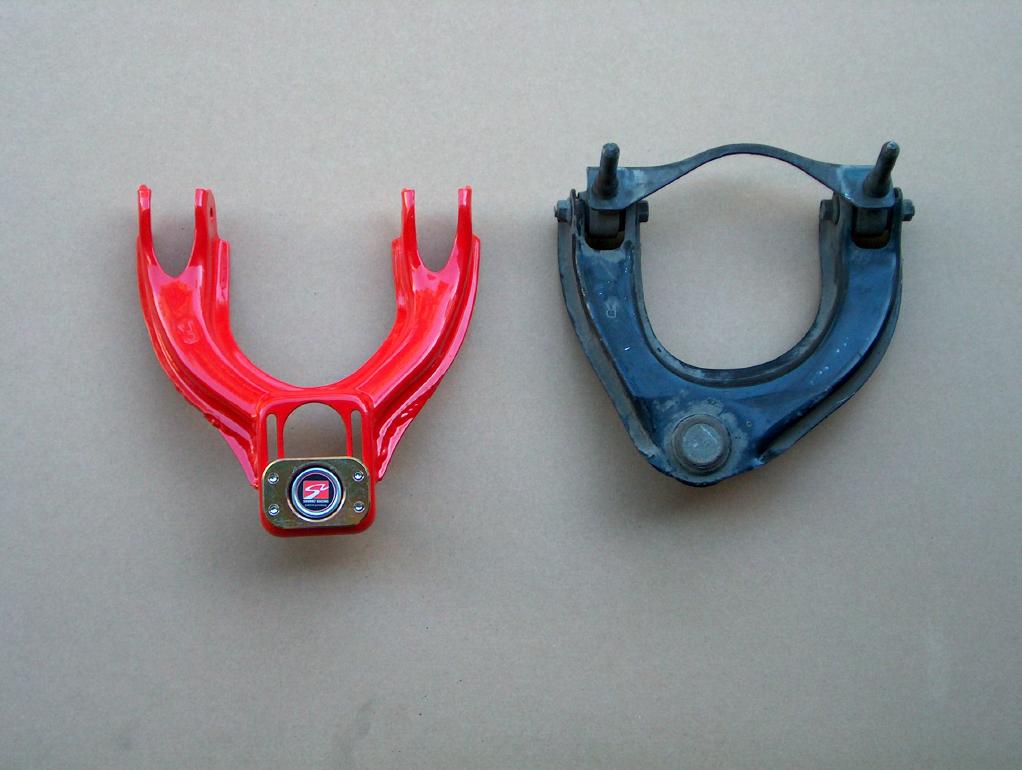
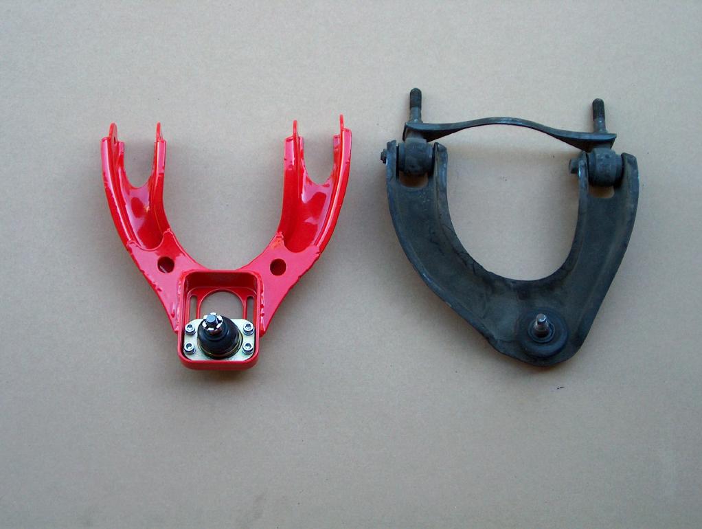
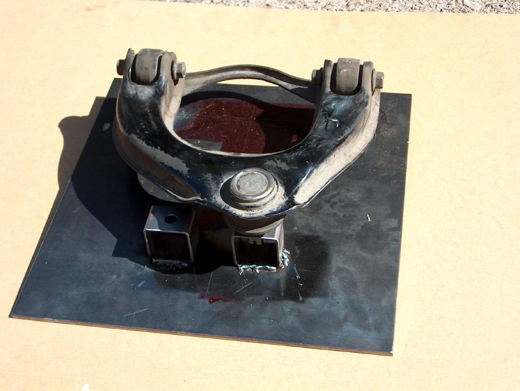
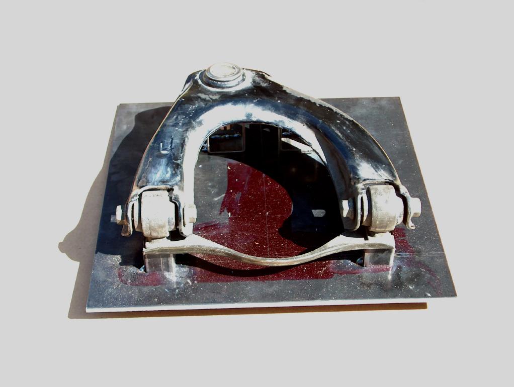
In the following two photos you can see the "new" design Skunk2 arms that fit the 92 civics and also a stock 91 civic arm. The "new" design has the bolts that hold the ball joint in place coming in from the bottom. This is a better design for several reasons. One is that in the old design, the bolts tended to spread the slots out. Another reason is that it's a lot easier to loosen and adjust while installed in the car.
I'm real impressed with the construction of the Skunk2 arm and to make it worse, you can get a pair from Lighting Motorsports for only $189. (tell Tom that you are planning on building some "Wes2" arms and he should give you a good laugh!)
It should be real apparent that you can't use the arms due to the placement of the ball joint (plus the spacing of the rubber bushings may be different).
So, the only thing to do is to get out the welder!!!! God I love a challenge.
Getting the parts;
I bought the Skunk2 arms, a thick 12" square steel plate, and a set of junk yard arms.
Cutting and welding;
Then I cut off everything from the Skunk2 that I didn't want. I hope that this photo makes you spoiled 5G Civic owners cry (spoiled bastards such as you are)!
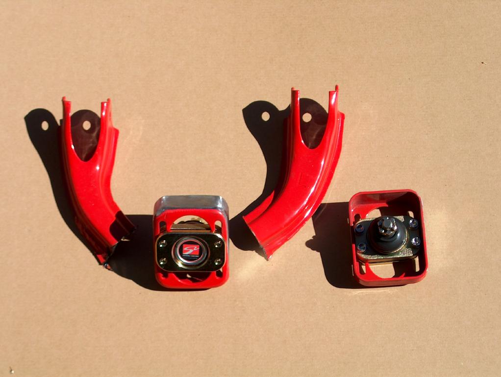
One of the quality things about the arms is that the "slider" receptacle section is a stamped section.
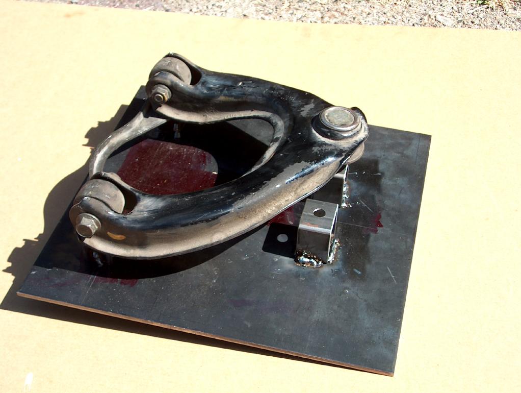
I then made up a jig from the original arms.
Now there are a couple things that you should notice in the photos.
The jig is set up to do both sides. The only difference is in the ball joint attachment point.
The "cross-bar" that goes from rubber bushing to rubber bushing was swapped side for side so that it was out of the way while fabricating.
There isn't a need for a tapered attachment of the ball joint. If you look real close at a ball joint, you will see a shoulder just prior to where it tapers and this is what it's tightened down against.
In the following photo, you can see that I welded a section of tube across the arm. The reason behind it was that I didn't know how much "arm" I'd have to cut away and I didn't want the two pieces flopping around independent.
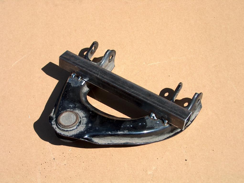
It ends up that this may not have been necessary, but I'd recommend it and would do it again. Once the new ball joint assembly was welded in place, I cut off the piece and ground the welds flush. (It's an old street rod trick used when chopping the top on a car)
Due to my not having a photographer, there are no photos of me cutting out the old ball joint, but it's easy to picture. (dang I sure wish I had a model!) I used a 4" Mikita grinder with cut-off wheel.
Adjust the Skunk2 ball joint so that it's 1" from the end of it's travel!!! This is done so that once installed, you will have 1" of travel beyond the stock position. It's in this position in all the following photos.
Mount the original arm in the jig and cut off the area around the original ball joint. Then swing the arm up and out of the way so that you can mount the Skunk2 assembly. Then cut away from the original arm until it can fit around the Skunk2 assembly. Tack weld it all together.
This is what you end up with prior to doing any finish welding. (unbolt the ball joint prior to doing any finish welding)
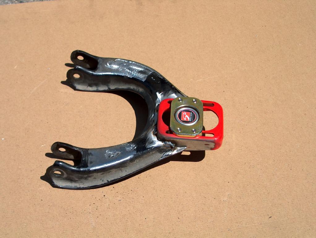
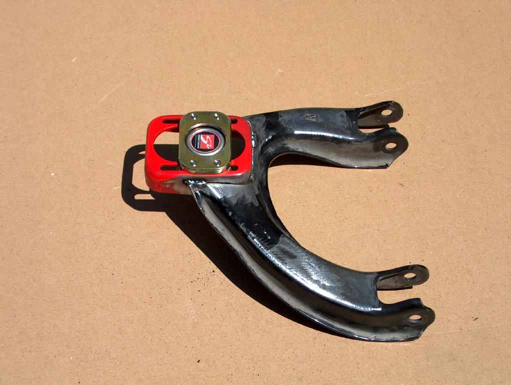
Adjustable EF control arms!!
Closing comments;
As I said at the top; there are still clearance issues that have to be addressed dealing with the inner fenders (upper frame area)!!!
I'm not building these for anybody. I already have a job and it has nothing to do with cars. It's just a hobby for me!
Have a qualified welder do all welding!!!!!
return to my site's entry page
Wes Vann