Chipping an OBD1 ECU
October 4, 2005
To start off;
If you don't already have them, you will have to buy some tools. The biggest thing is a good 25 watt soldering iron.
If you want to know what you are doing, you will have to do some reading and researching of sites other than mine! All the information you need is out there and fairly easy to find. Go to pgmfi.org and look around! Print out anything helpful and read several times!
(12/18/07; It seems like the pgmfi.org site has gone down. That's real sad due to the amount of information that was there!!!)
I'm not going to go into a whole bunch of specifics cause you can find the information elsewhere. As an example, I'm not going to say what value capacitors to use cause they come with the kit I'm going to recommend you buy.
Some of what I'm going to show may not make sense due to the fact that the ECU that I bought already had the conversion done. I just didn't like how it was done and re-did it.
Most of the photos are "clickable" to a larger version.
Why chip an ECU and what does it mean?
I don't know who figured it out, but it seems that Honda designed the ECU so that it's possible to insert a second ROM that can be selected to work in the place of the original ROM. If jumper J1 is connected, the second ROM is used (I'm going to call it the "secondary ROM"). If jumper J1 is removed, then the ECU uses the primary ROM.
Of course, you have to know what a ROM is! It stands for "read only memory" and it's easiest to think of it as a bunch of tables where data is kept. All of the fuel curves and ignition timing is stored there. If you want to change how the engine runs, you have to be able to change those things.
So, the idea is to be able to put in a ROM with different settings than stock. That's called "chipping".
It only takes a couple of parts and you should just buy the kit from Moates.net! Go to his site and buy the "UBER1 UberData modification kit" for only 15 bucks. All the hard parts are there and the quality is the best you will find. It doesn't get any easier!!
You will have to get the ROM programmed or you can do it yourself, but you will have to buy a "prom burner". You can get the initial data from PGMFI.org's site and modify it as required.
A couple quick comments;
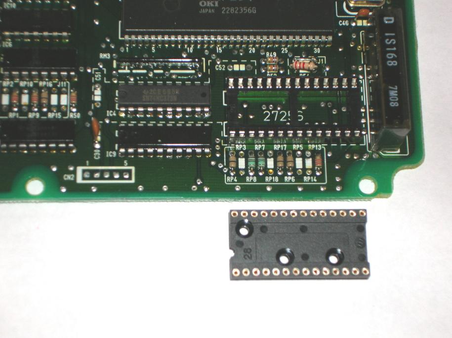
Don't use cheap parts. One of the main reasons that I decided to re-do this conversion is that it had a cheap socket for the rom. In the following photo, you can see the socket that was used and also the new one that came with the Moates kit. If the ROM can't make good contact, the car will not run and a friend had that very problem with an ECU that had this type socket.
Another issue was that the soldering wasn't all that good and wasn't cleaned up afterwards.
Now it may just be that I'm a picky bastard but I worked in the computer industry for quite some time and just had to re-do it.
Doing the work;
Remove the top and bottom cover plates.
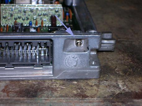
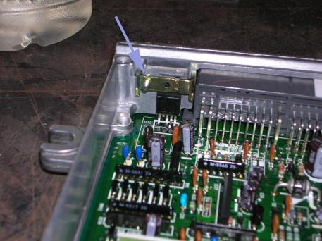
Then remove the screw pointed to in the photo on the left. It hold a plate that clamps a transistor to the frame of the ECU (to keep it cool). The photo on the right shows the plate.
Now remove the screws that hold the circuit board to the frame and remove it.
This photo shows where the items are that needed to be added go.
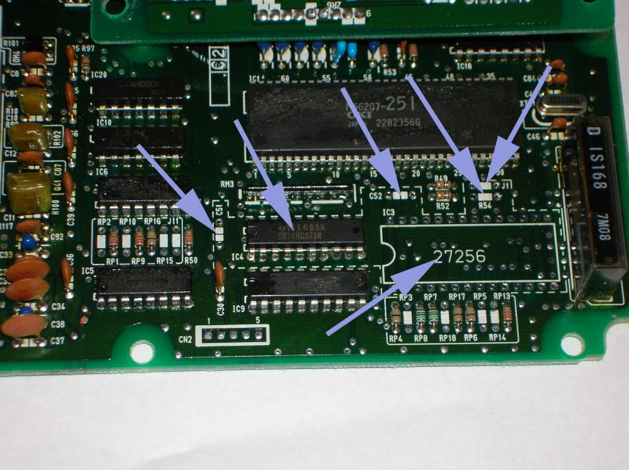
It may be misleading because one of the IC's is already installed. You are going to add 6 items. They are; two capacitors (C51 and C52), one resistor (R54), a jumper (J1), an IC (IC4), and then the socket for the ROM (IC3 27256).
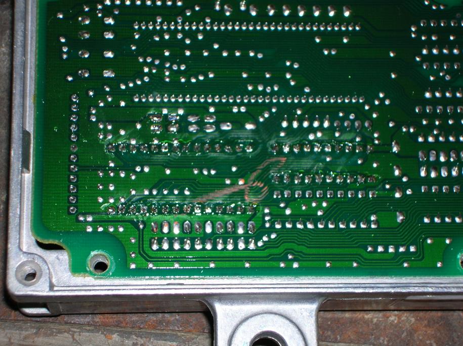
In order to add the items, you have to first clean out the holes in the circuit board. You could buy a solder removing station or just use SolderWick as I'm doing in the following photo.
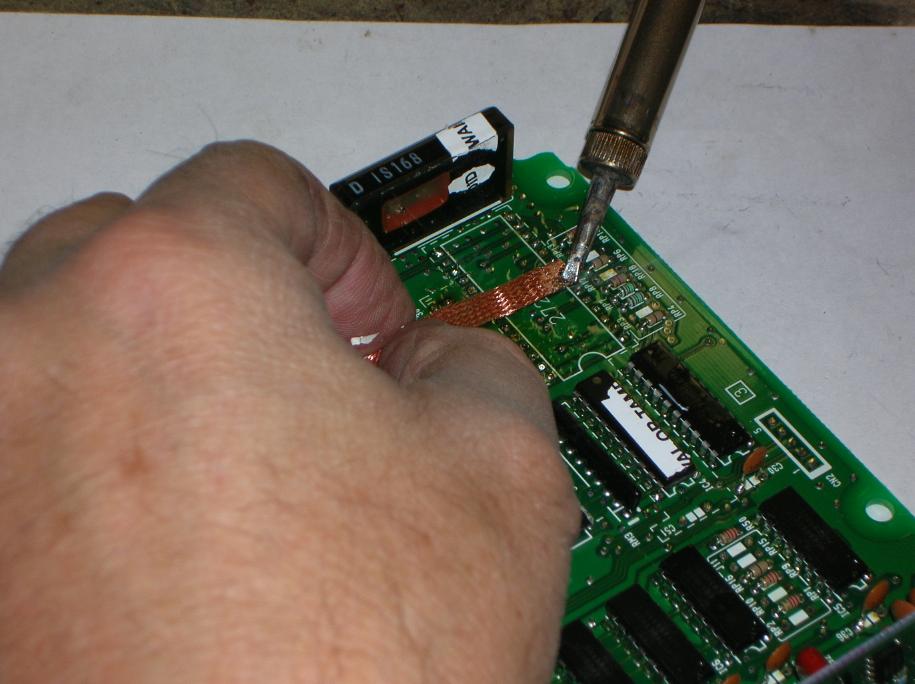
SolderWick is a brass braid that comes in a role. It sucks up the solder. You first put some liquid flux on the circuit board. Then put some liquid flux on the end of the SolderWick. Place it on the area where you want to remove the solder and then put the iron on it. When the soldering iron melts the solder, the Solderwick sucks it up by capillary action. It's not hard but you have to play around with it a bit.
Here are all the parts that come in the Moates kit.
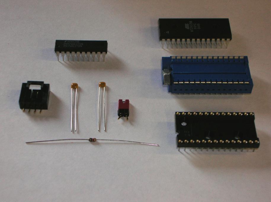
That blue item is a "zero insertion" socket and it has a little lever on the side that allows you to remove and replace the ROM easily. (in order for the lever to clear some of the other items on the circuit board, you have to use the black socket to space it upward)
That little goober with the red top is the jumper for J1. Once installed, you can just pull off the red section to "open" the connection.
The big IC at the top of the photo is the ROM that you will have to get programmed.
Once again, I've got to say that I love this kit! The parts are all top quality and it's only 15 bucks to get all the correct stuff at one place.
Once all the holes are open, clean off the board with isopropyl alcohol and a fairly soft brush.
Insert the parts and solder them in place. Use plenty of liquid flux. (IC's have to go in the correct way or you will burn them out. Notice that there is a "notch" on one end of the IC and match the printed lay-out on the board)
Then go and clean the board again with the isopropyl alcohol.
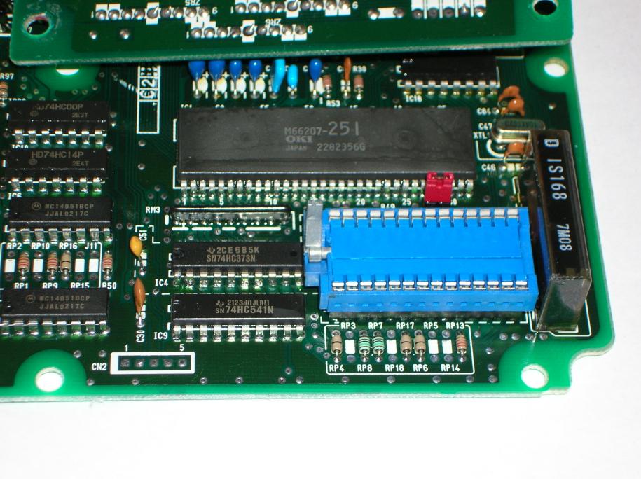
This photo shows all the stuff soldered in place.
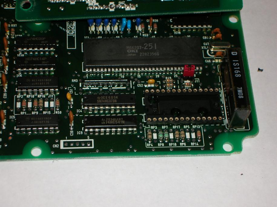
And this one shows the ZIF socket in place, ready for the ROM.
Now just put the whole thing back together.
Closing comments;
Be careful about static electricity!!!
return to my site's entry page
Wes Vann