Building a Cross-member
Originally written; April 8, 2007
To start off;
If your welding is questionable, you should have somebody else do it for you!
When I first did the engine swap in my car, I used a Place Racing cross-member and I was never happy with it. The ground clearance was shit (and my car isn't that low) and you couldn't jack up the car from the center of it without it flexing.
I've never felt the need to have a cross-member that uses heim joints. Plus there are none out there that would do what I wanted or were designed the way I felt they should be.
What finally got me off my ass to do this was that I had a clunk in the front suspension that ended up being movement between the cross-member and the chassis. The bolts were tight, but could have been tighter. I've got a theory as to why I had a problem, but it's just a theory (and I'll get into it latter).
I'm sorry if this page down loads slowly, due to the size of the photos, but that's just the way it is!
Building it.
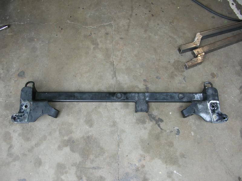
Here is a photo of the original Place Racing cross-member.
Now if you say that you can't do what I did due to Place Racing being out of business, then the answer is to just buy a cross-member from a company called Innovative.
The issue is that just about everybody places the cross bar below the radiator. To give as much ground clearance as possible, the cross bar is only one inch high (it's a 1" by 2" by 3/16" rectangular tube). The two circular pieces are for a 1/2 wide radiator if you wanted it. The flange near the center is for the front engine mount.
In the upper corner of the photo you can see two "bent" tube sections. The lower one is the "test" tube that I made up to check clearances and for required dimensions. The "test" tube is thin wall tubing and as a result is easy to fab up. The upper tube is the one used and is 1 1/2" by 1 1/2" by 3/16" square tube.
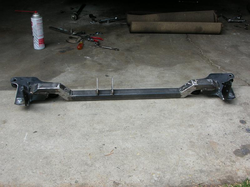
In the next photo, I've welded in the new cross tube.
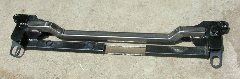
The main section of the new cross tube goes below the radiator hose and behind the radiator lower tank. (I'm running a full width DA radiator)
By welding the new cross tube in place before cutting out the original tube, the end pieces stay in alignment and the width will not change. The reason for the cut out section was to allow a certain amount of flex. The two end pieces were not in a level plane with one another and I clamped a rigid tube across them to hold them true while welding in the new piece.
This photo shows how I've started to cut off pieces I don't need.
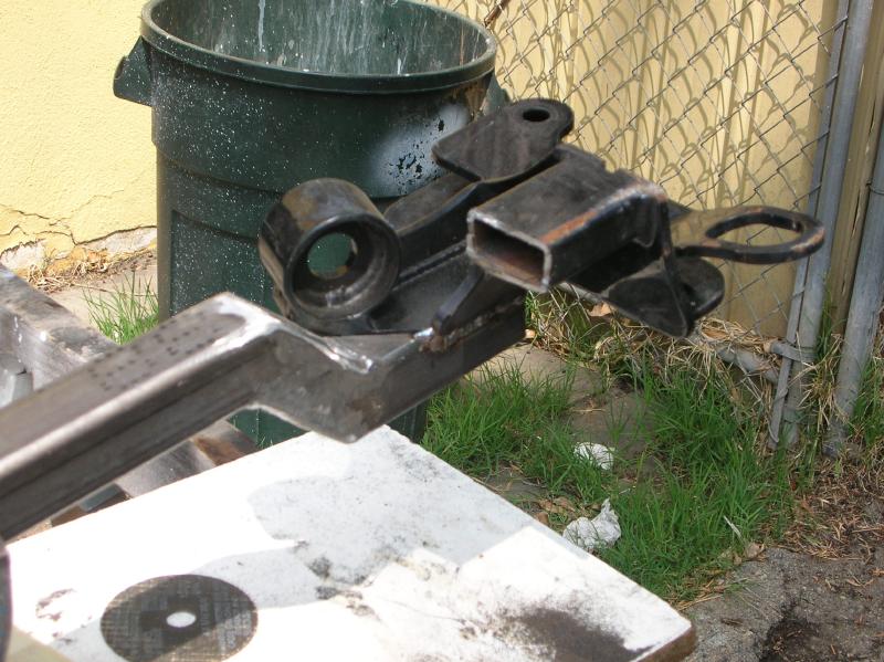
I don't want the old cross pipe or the "tow" tie-downs.
I really wish I had a plasma cutter. It would have made this process a lot quicker. I do have a cutting torch, but thought the heat would lead to distortion. As it is, I used a lot of 4 1/2" cut-off disks on an angle grinder.
Here I've got a lot of stuff cut off and is a good photo showing what is happening.
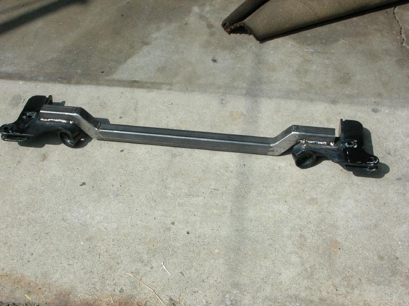
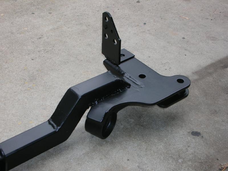
Here it is with the flanges for the front motor mount welded on.
I've also angled off the ends of the cross pipe and added closure plates.
You have to look close but at both sides you can see two brackets that I fab'd up from original factory tow brackets. They are made by cutting the factory piece short and then welding on a plate so that they can be bolted to the cross-member.
This photo shows the finished passenger side viewed from the top.
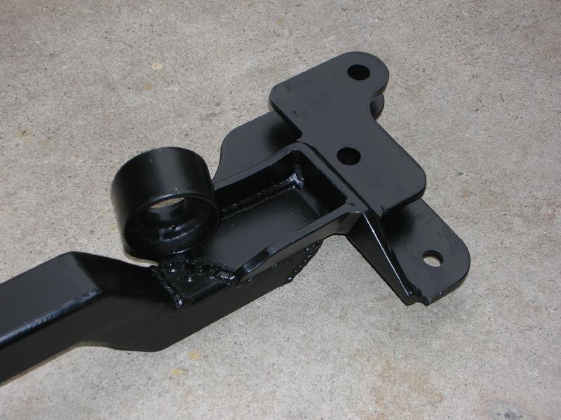
And this photo shows it from the bottom.
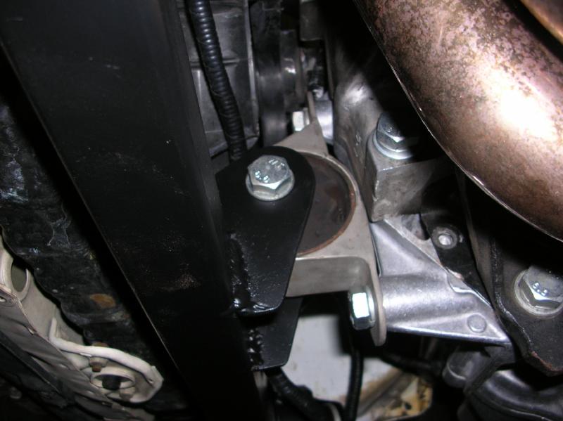
The next two photos show the installed bar on the passenger side (the control arm bushing is just sitting loose)
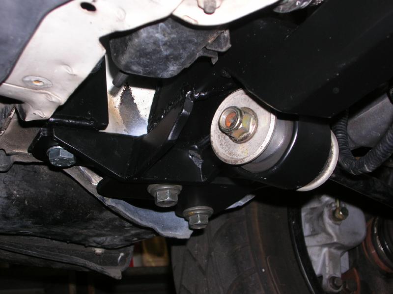
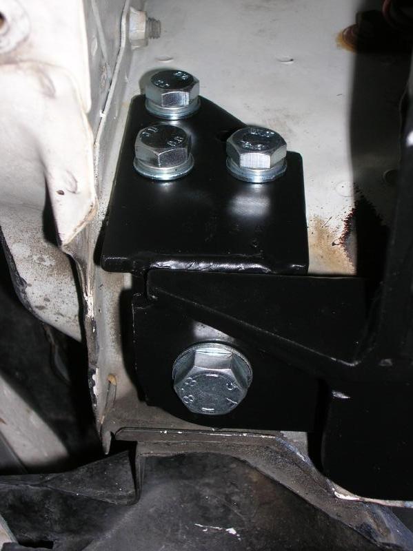
Notice how using the modified "tow" bracket gives me additional anchorage for the cross-member. What can't be seen in the last photo is that the bolt going through the cross-member and the "tow" bracket has a nut (and lock washer) on it. The bolt doesn't go into chassis and the nut is easy to get to due to the shape of the chassis at this area.
The next two photo give a better "over-all" idea on the bar placement.
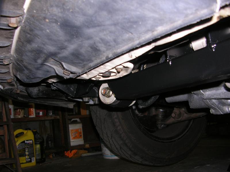
Notice that the bar is no lower than the control arm bushing (same as the factory cross-member).
Notice that the bar is behind the radiator bottom tank and not below it!!
So how's it sit? Well, here is a photo I took, sitting on the ground in front of it.
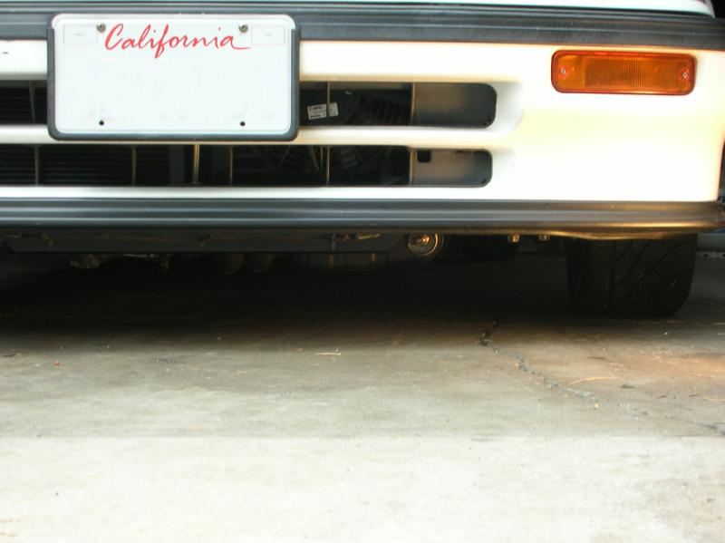
I had to use a shop light to illuminate it.
And I can now jack up the car from the center of the cross-member with no notable deflection!
Closing comments;
The reason that I started this whole project was due to there being a "clunk" in the suspension when starting out or braking. With the help of a friend, I finally figured out that the cross-member was moving in relationship to the chassis.
I found that although the bolts were tight, they could have been tighter.
Now what's interesting is that both the factory and aftermarket cross-members have play in the holes that the bolts go though. They have too due to manufacturing tolerances.
What is different between the original cross-member and the aftermarket one is that the factory one has a raised area around the bolt hole. As a result, all the clamping force provided by the bolt is in a concentrated area. On the aftermarket one, the clamping force is spread out over a wider area. As a result, the aftermarket cross-member would see a smaller psi (pounds per square inch) on the contact surface.
In order to have it the same as on a factory one, I placed fender washers between the cross-member and the chassis (I also tightened the hell out of the bolts this time).
Three days of fabricating and I've finally got exactly what I wanted!!!
return to my site's entry page
Wes Vann