Making conversion mounts that have rubber bushings
(B18C in a 89 civic)
February 7, 2004
The history (how and why);
I just can't understand why people would buy conversion mounts that transmit excessive vibration due to the urethane bushings!!
Over the years, I've had to fabricate all sorts of things and just couldn't believe the there wasn't a reasonable option. I wanted a rubber bushing and started the search. I was looking for a molded rubber bushing that had a metal outer shell and also a metal sleeve for the bolt to go through. There wasn't anything that I could find that was a factory mount that I could "convert.
A friend of mine runs a street rod shop and he recommended that look at the bushings that are in the rear of a Jaguar. And so, it was off to the Jaguar dealer.
What I found was perfect! It's a chassis bushing (MNA2370AA) for the newer Jag's. The only thing that had to be worked around is that the center sleeve isn't in the center. That wasn't a problem due to the fact that I was fabricating the mounts.
At this point, I purchased a set of Place Racing mounts along with the front cross-member (with it's mount). I was going to copy them dimensionally. I don't have any problem with this due to the fact that I'm not going to sell mounts.
Then came the visit to Industrial Metal to buy the steel required. I got normal steel for the jigs and stainless to make the mounts.
One thing that I have to admit; I'm not a professional welder, and my welds show it!
Most of the photos can be clicked to go to a full screen version of the photo. Use your back button to return here.
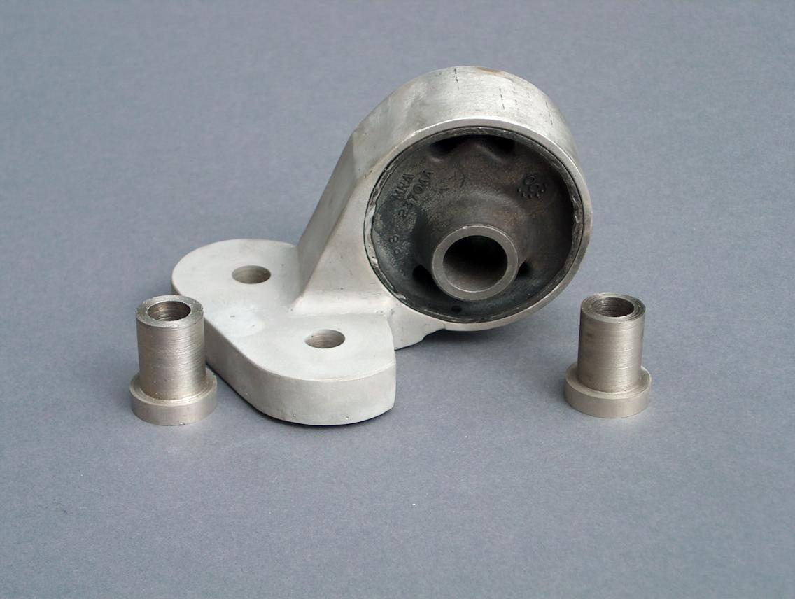
The mount "outer ring";
I purchase some thick wall stainless steel tube and then turned the inside diameter so that the bushing would be a snug fit.
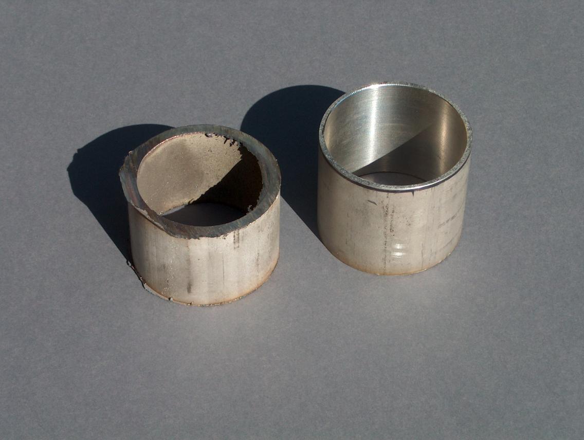
I made up a total of 5 of these. Four of them would be for the mounts. The other has a slightly larger inside diameter and I can use it if I have to press out the bushings. The tube on the left is what I started out with.
The "collar's;
The inside diameter of the metal sleeve within the bushing is smaller than the mounting bolt (12mm). As a result, I made up collars out of stainless steel to adapt them. They have a shoulder to set up the correct width. Another point is that they are slightly "short" so that when the mounting bolt is tightened, they don't bottom out against one another. Once the mounting bolt is tightened, it should clamp the bushing tight.
You can see some of the collars in the photos that are farther down on the page.
The jig's;
Using 12"x12"x1/4" steel plate as a base, I made up jigs from the mounts that I had. All four jigs are different due to all the mounts being different. The photos show the jig for the transmission mount. During the fabricating, the outer sleeve of the bushing was tack welded to the stainless steel tube.
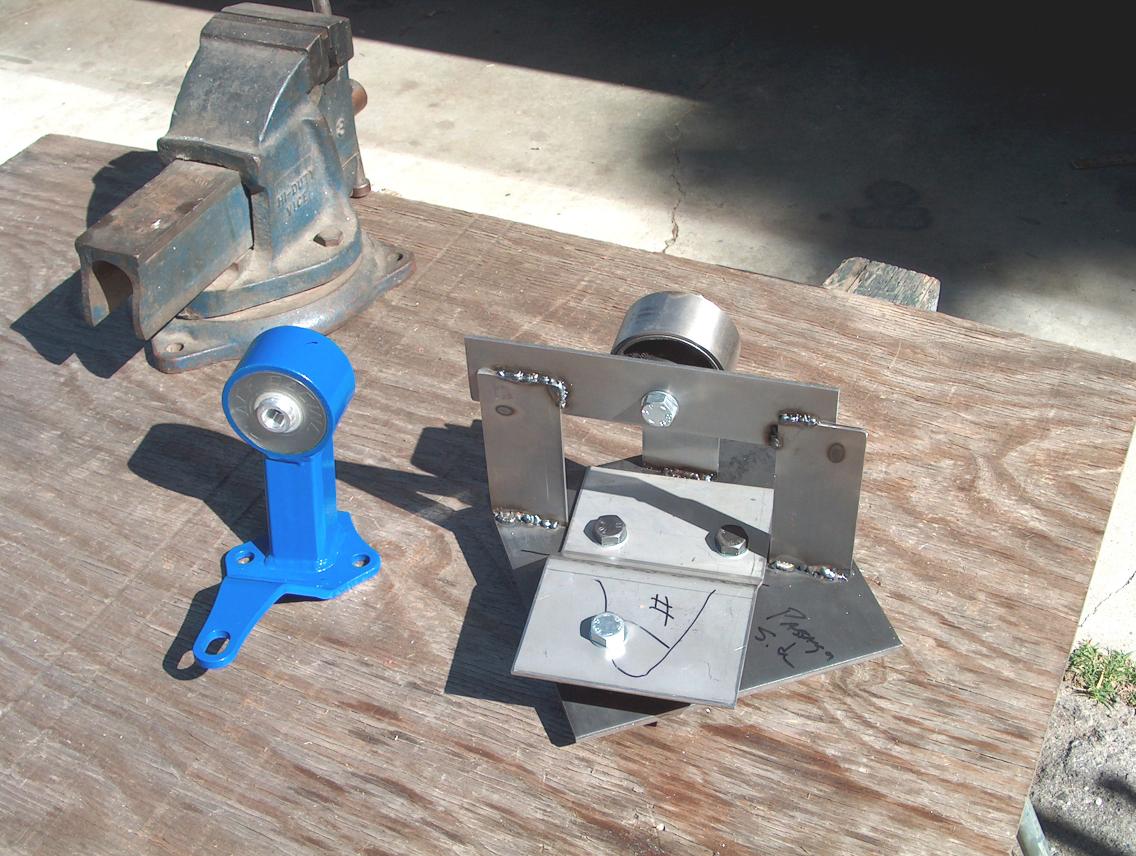
The two above photos show the original mount, the jig, bushing with metal tube, and the base of the new mount. At this point, it's all a matter of making the stuff that goes between.
Fabricating;
I had the bottom plate bent at a fabrication shop (bending stainless steel is extremely difficult!!). All the other work, I did in the garage.
 "A"
"A"
 "B"
"B"
 "C"
"C"
 "D"
"D"
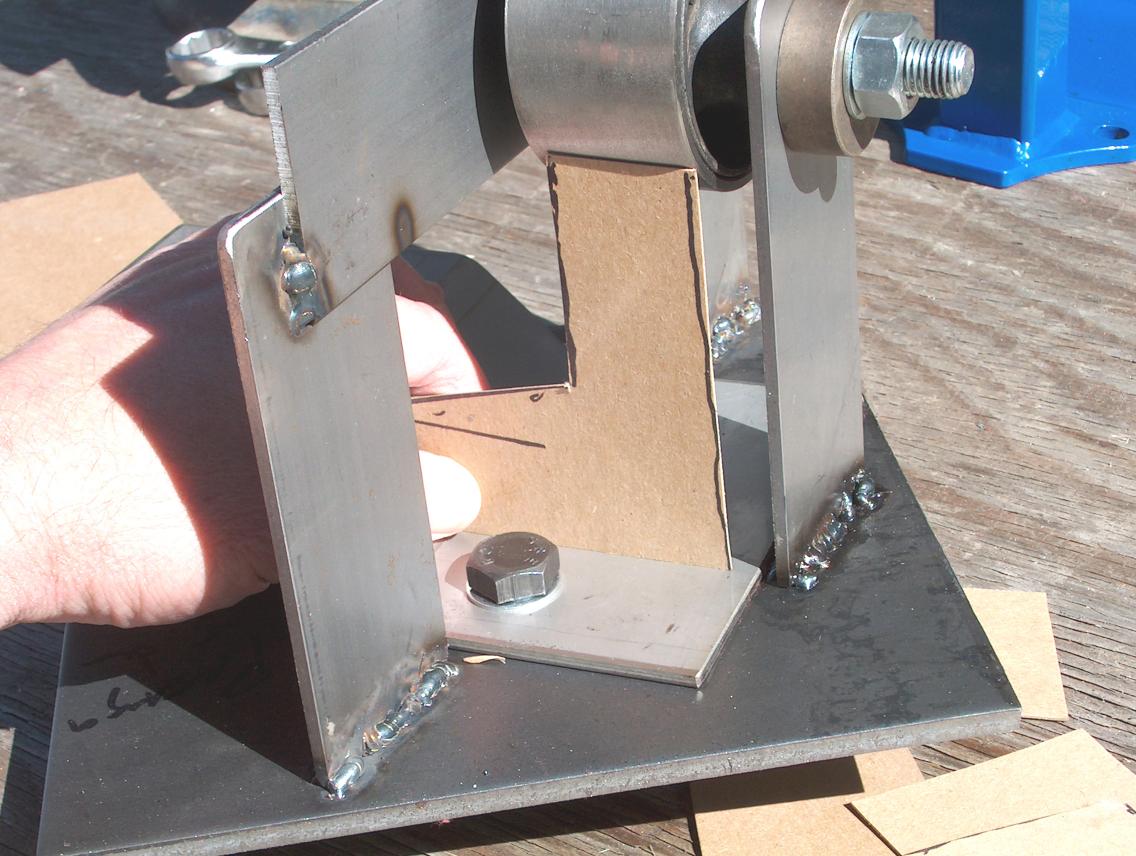
When working with metal, it's always easiest to first make it out of cardboard or illustration board. In photo "A", I'm holding a piece that I've cut out using scissors.
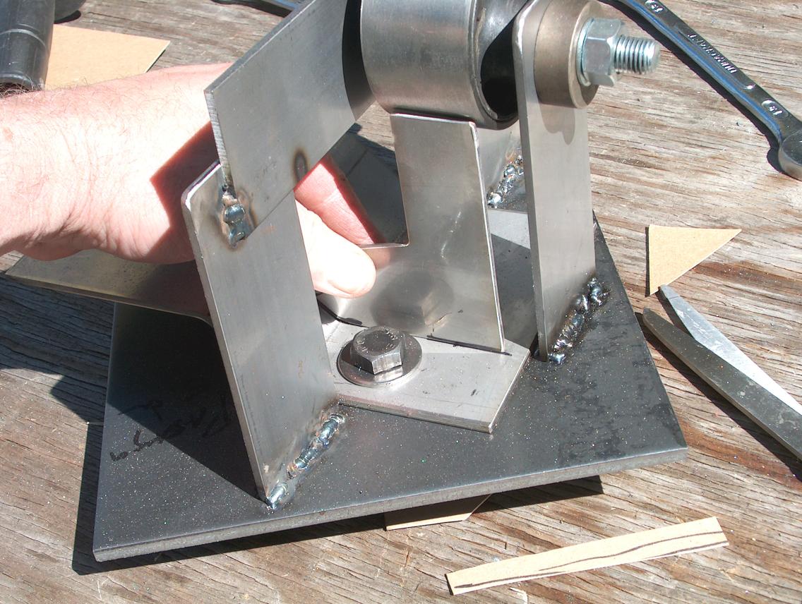
Using a 4" Mikita grinder with cut-off wheel, I then cut the stainless steel side plate to match. In photo "B", I'm holding it in place.
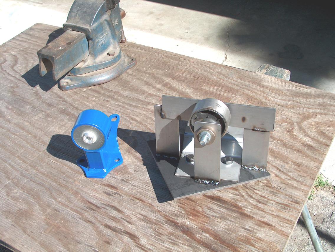
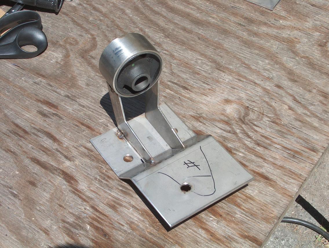
Photo "C" shows the preliminary mount removed from the jig. At this point, there are just the two side plates in place.
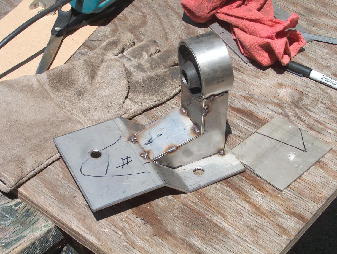
In photo "D", I've started adding the closure plates.
Once that's done, it's time to do a whole bunch of welding and cutting down the base plate to something reasonable. Prior to doing the finish welding, I ground off the tack weld holding the bushing and removed it.
After doing all the welding, the tube that holds the bushing distorts enough that you have to "press" in the bushings.
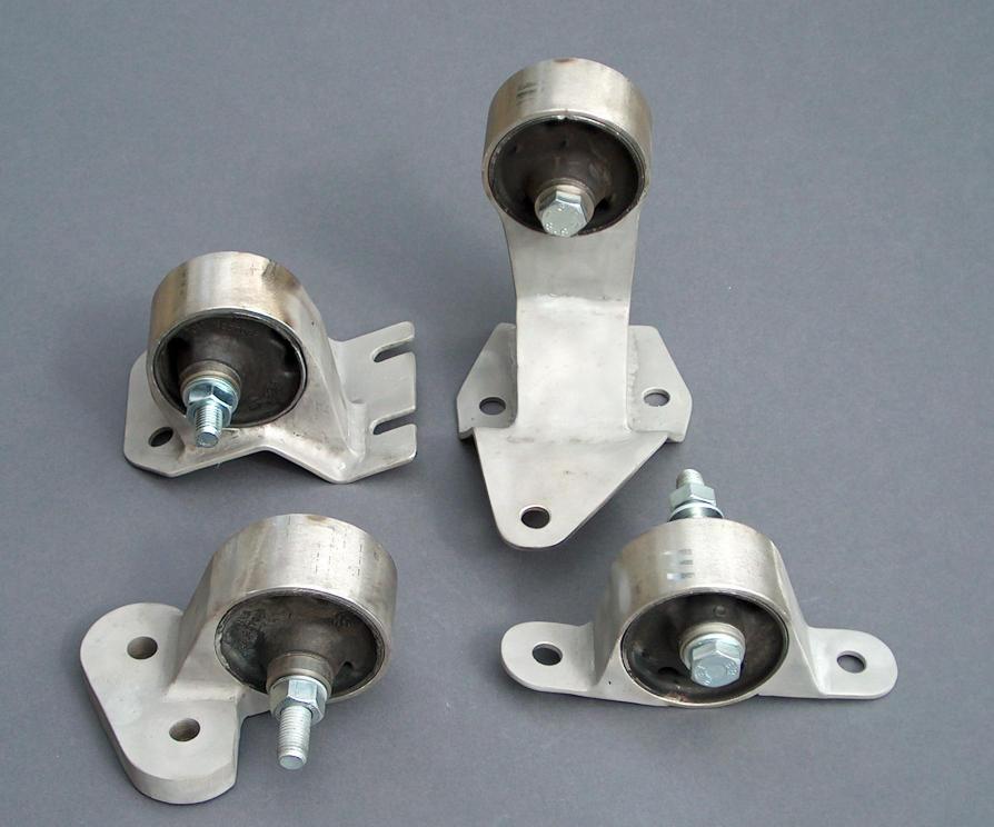
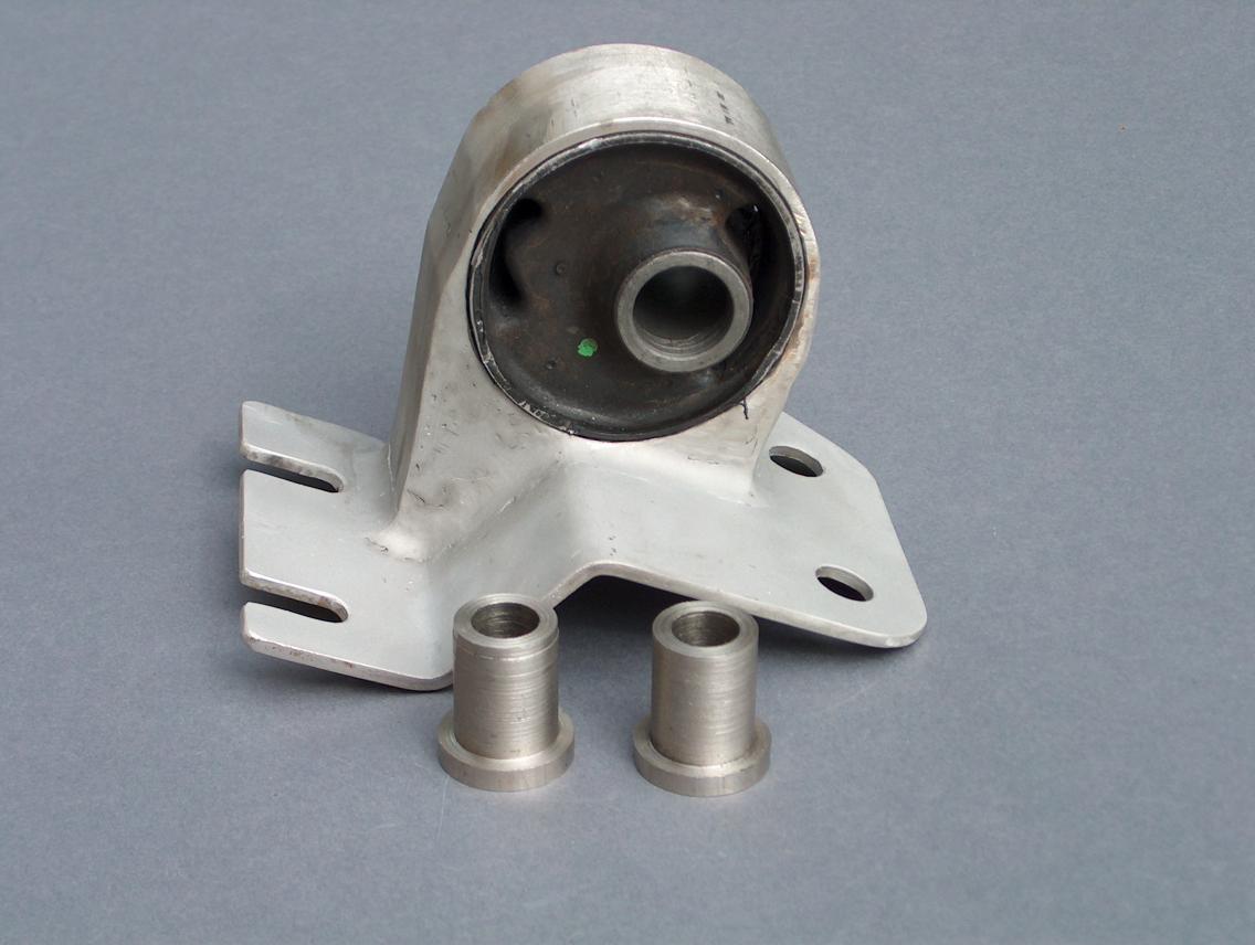
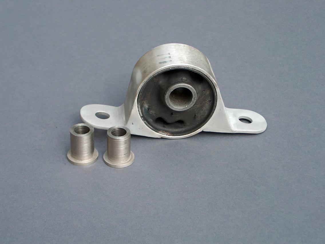
What do they look like;
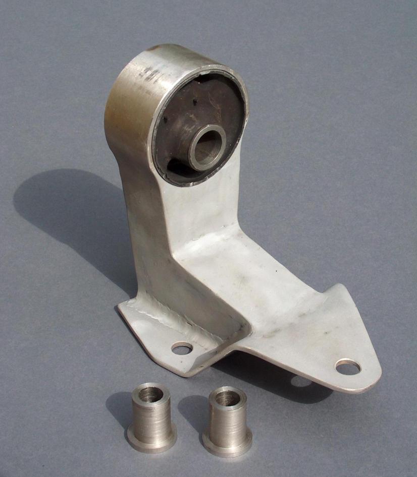 "A"
"A"
 "B"
"B"
 "C"
"C"
 "D"
"D"
Photo "A" is the transmission (passenger side) mount.
Photo "B" is the drivers side, engine mount.
Photo "C" is the rear mount.
Photo "D" is the front mount and is for the Place Racing cross-member.
Final notes;
So, how do they work? I don't know due to having just bought the car that they will be used on. The B18C waits. I'll update this page once everything is together.
return to my site's entry page
Wes Vann