Building Radius Arms for Clearance
Originally written; April 22, 2006
To start off;
I'm posting this information as "food for thought"!
The safety issues in regards to building and using custom radius arms shouldn't be take lightly. You will notice that I've not posted exact sizes of the metal parts used. That's intentional and what I'm doing is make the individual that decides to do this thinks it through on his own!
In some EF engine swaps, there are clearance issues with the radius arms.
The problem comes about due to a variety of reasons and it's not worth trying to define why. It just varies from car to car. When swapping around engines, stuff like this just happen.
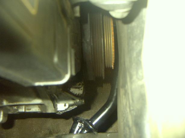
A friend of mine (Adam, aka Mr_CRX) brought up the situation on his CRX and it got me thinking (not always a good thing). His problem was that when lowered, his radius rod would hit the pulley! On my hatchback, the problem isn't as bad and a solution really isn't needed, but it's close.
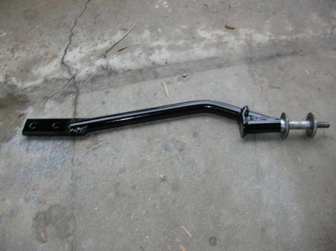
So, this is what I came up with;
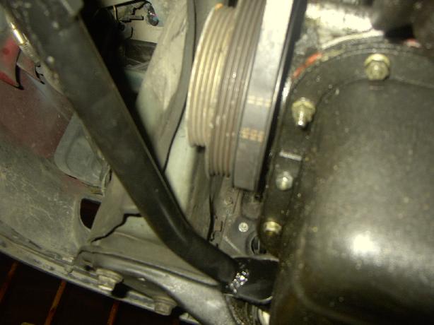
Here are two photos of the bar installed on Adam's CRX;
Of course, this is pretty much jumping the gun in regards to how it was done.
How to figure out the shape required;
After crawling under the car and taking a bunch of measurements, I used my computer to draw up the desired shape. I printed several copies and sent the to Adam so that he could do what I'm going to show you next.
In the next photo, I've glued the printed shape on a piece of foam core. Foam core is available at any art supply and it's pretty much what the name says. It's a thickness of foam with heavy paper on each side. I had Adam due the same thing, but with cardboard. I used 3M Spray-mount to glue it to the foam core (it's spray much like contact cement).
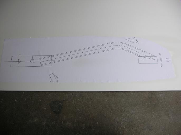
Then I used an exacto knife to cut it out.
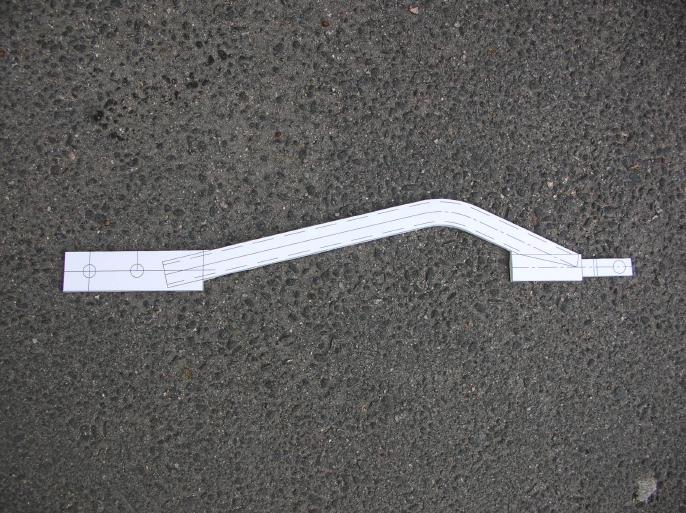
The whole reason for doing this is to have something that you can hold under the car to see if the shape is correct. It's a LOT easier than building up a whole bunch of them out of steel.
I don't want to hear anybody say; "but Wes, I don't have a computer to do the drawing"!!! You could just as easily draw it by hand and then have a bunch of zerox copies made.
Once Adam let me know that the shape would work, it was time to start playing around with steel.
Making a jig;
I went and got a radius arm from the junk yard and made the jig shown in the following photo. Not much to say, it's pretty much straight forward.
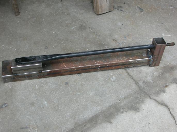
Although not shown in the photo, it bolts done solid. It should also be noted that the shoulder at the threaded end of the bar sits flush with the square tube section. This defines the length of the built bar!
Building the arm;
Here is a photo of the steel "stuff" that I bought to build up four arms (one set for Adam and the other set for me). Some of the items have already had work done on them.
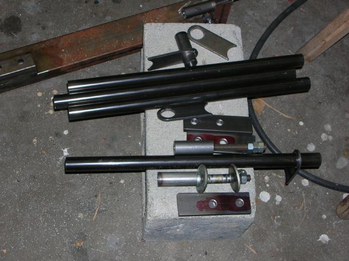
The following photo shows the round stock that has been drilled out and tapped for 12mm, 1.25 threaded rod. (I bought the threaded rod from McMasterCarr). It also shows one of the chassis brackets that I bought and drilled out to a larger diameter.
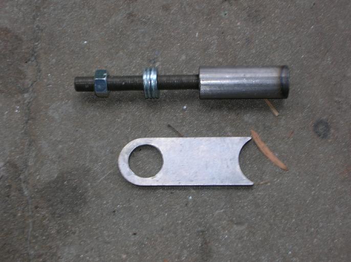
The threaded rod goes into the round stock and is "lock-tited" in place.
The next photo shows the beginning of the arm being built on the jig.
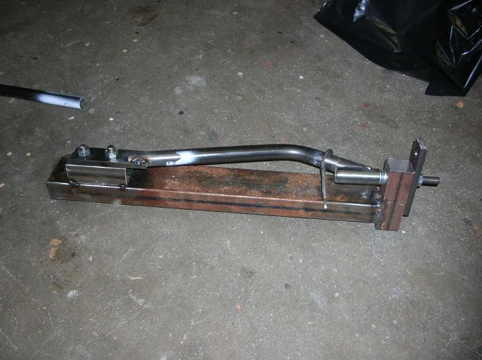
There are a couple things that should be noted in the above photo!!
The first is that there are four washers at the end where the threaded rod is. The reason is that by adding or removing washers, a limited amount of caster adjustment can be done. When I gave the finished arms to Adam I made it real clear that if he wants the stock length, he HAS to use the four supplied washers.
The other thing is the location of that chassis bracket. Notice that when the photo was taken, it's still loose. The reason is that you want to weld around the full contact surface between the bent tube and the round stock section. Then the chassis bracket is added and welded in place. By doing this, you prevent the two round pieces from pulling apart (a major stress point if not reinforced)!!! The arms look a lot better without the chassis bracket but I wasn't willing to risk it.
Following is a photo of the finished arm.
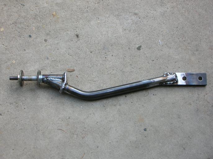
Notice that I "shaped" the chassis bracket.
And then the last photo shows one of the unfinished arms next to a stock arm.
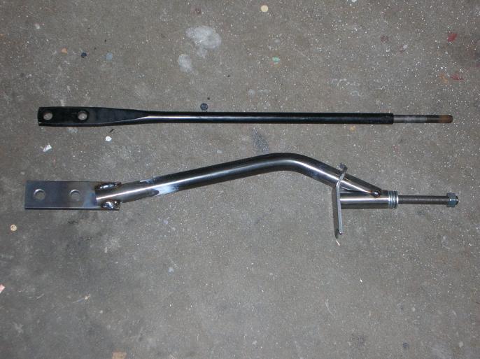
Now keep in mind that photos can make items look like they are not the same length!! The fabricated bar (with the four washers) is the same length as the original one.
Closing comments;
Adam has said that the tires will rub on the bar at an extreme steering angle. It's a "tight turn in a parking lot" type thing. Maybe it's possible to change the shape to make it better, but I'm just too tired to think about it.
I built these arms for Adam for free. At this point he owes me some ECU work.
Have a qualified welder do all welding!!!!!
return to my site's entry page
Wes Vann