Shortening The Shift Linkage
March 1, 2004
To start off;
I'm installing a B18C in a 89 Civic using motor mounts that dimensionally are similar to the ones sold by Place Racing (I'd place a link here, but their page is nothing other than a title page and has been that way for almost two years).
When doing this, you have to modify the shift linkage rods from a 90/93 Integra (or similar). One reason is that the length is too long. The other reason is that the attachment at the transmission is different.
The length that you have to shorten the linkage depends on who's mount kit you use. The Hasport kit places the engine closer to the firewall than the Place Racing kit.
Of course, you could just buy new shift linkage from the mount manufacturer that is specific to their kit.
Most photos will be "click-able" to view them larger. Use the back button to return here.
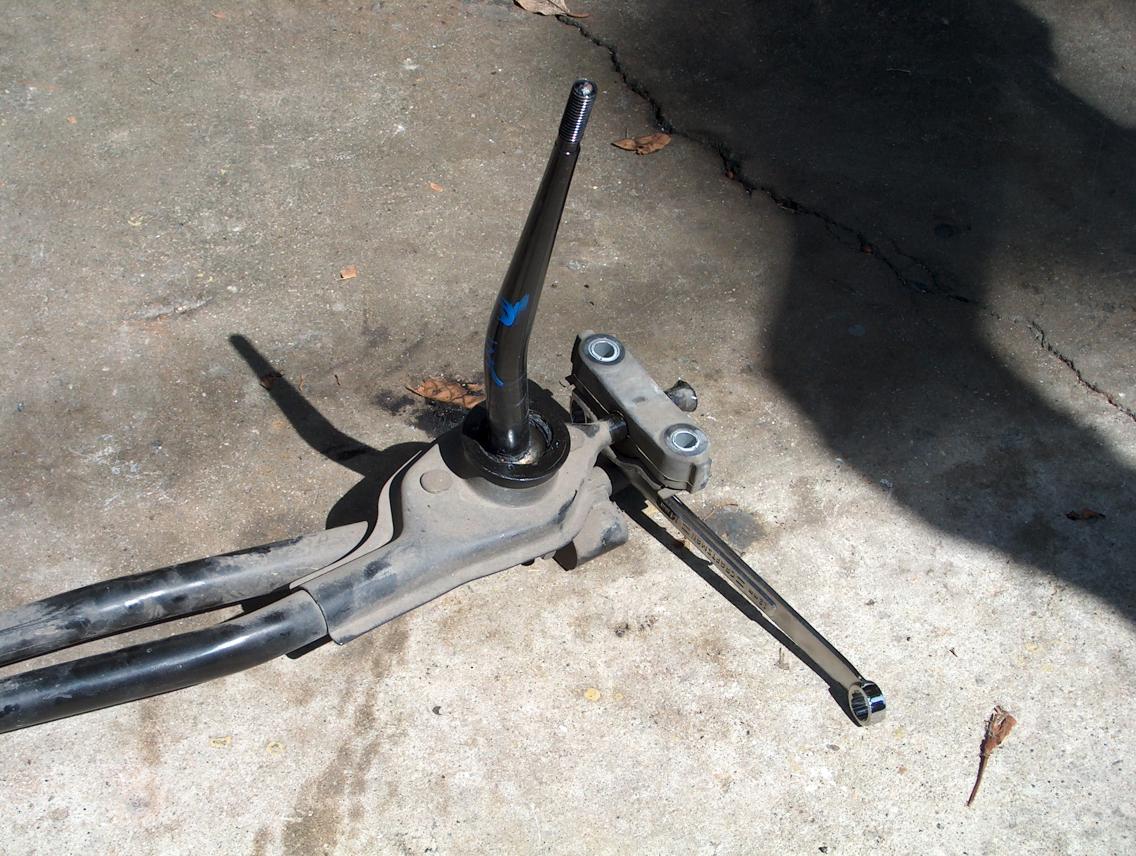
The "how's and why's" of the linkage;
There are two arms that make up the shift linkage. One is the torque arm and it mounts on the transmission body, is the socket for the shift lever pivot ball, and also is supported at the body near the shift lever.
It's real important to know that the torque arm sets in a rubber bushing and can slide fore and aft. The reason for this is to negate any movement of the engine. As a side bonus, the amount that you have to shorten the linkage isn't critical.
What is major critical is that both arms are shortened the exact same length and that each section isn't rotated when welded back together!
Once shortened, the pivot ball should be centered in the hole in the floor board and the section of the torque arm that goes into the rubber mounting bushing isn't "bottomed out".
How to shorten it;
Do the torque arm first!
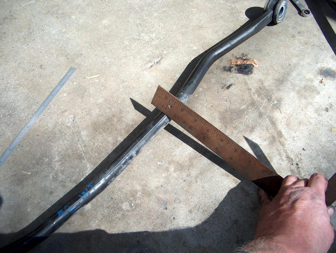
What I'm doing in the photo on the left is use a straight edge to scribe a line through the paint while holding the arm from moving. If you don't do this prior to cutting, you are in trouble. Do this at a straight section of the arm.
In the photo on the right, I've scratched two lines four inches apart. These are reference lines. (click on the photo to see it better)
I then used a chop saw to cut the arm at one of the marks.
Then I installed the two sections under the car. Position the rear section so that the shifter pivot ball is centered in the floor board hole. Use a scribe to mark how much to cut off so that the two pieces line up. Remove everything.
Measure how much you plan on cutting off and write it down! Don't trust your memory. In my case, it was 1.55". It may be different for you. And yes, I really did write it down.
Cut off the section.
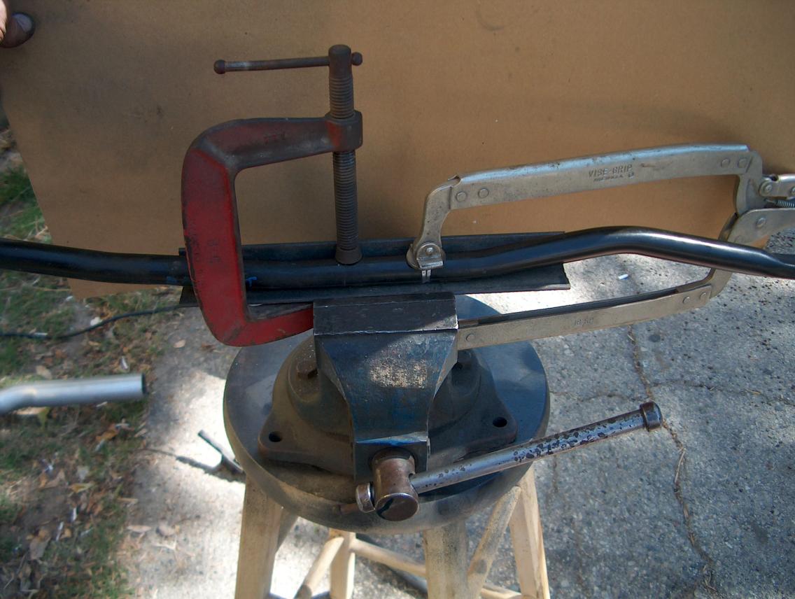
Weld it back together.
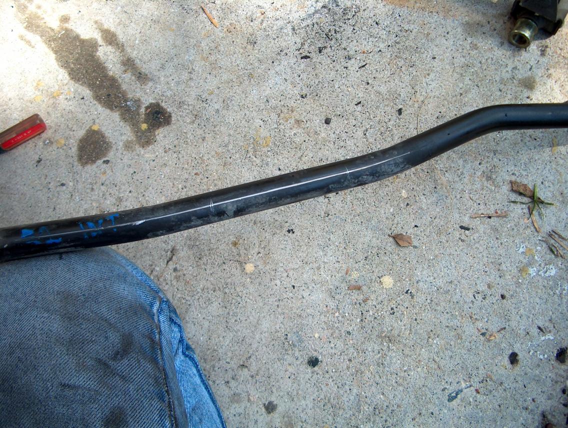
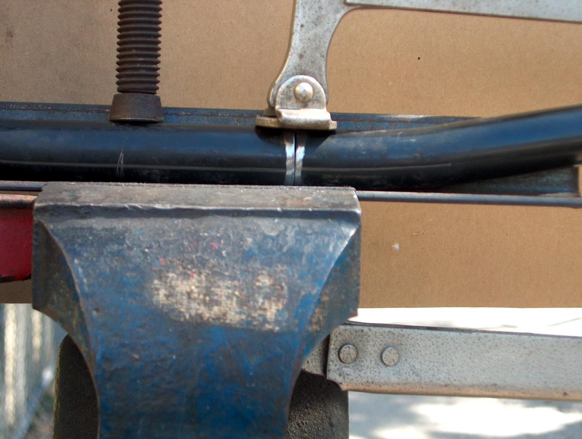
Now here is a fabricating tip; due to the fact that you did your cut on a straight section, you can use a piece of angle iron to hold it back together while welding it. If you look real close at the photo on the right, you can see how the line I scribed on it lines up, that way you know you haven't rotated the two pieces. (if you can't see it, click on the photo)
Next you do the same thing to the shift rod. Scribe the long line first!!! Just cut it the same length (that number you wrote down).
Clean up the welds and then spray some paint on it so it doesn't rust.
Closing comments;
Use jack stands!!! Use welding goggles!!
Now here is an interesting idea; There is no reason that you couldn't move the shifter more toward the rear of the car, making it easier to reach. You would have to move the rubber mounting bushing rearward and also may have to open up (or relocate) the hole through the floor board. This is something that I may do at a latter date due.
Another possibility would be to rotate the shift arm when welding it back together. This would cause the shifter to "tilt" to one side or the other.
If you didn't cut the shift arm the same length as the torque arm, it would "tilt" the shifter fore or aft.
return to my site's entry page
Wes Vann