Installing a Skunk 2 manifold
on a GSR head
February 7, 2004
The history (how and why);
I was given a B18C long block (a long story) and it didn't have any of the intake manifold stuff with it. I purchased from a local speed shop a fairly complete GSR manifold with most of the parts still bolted on it. As a result, I didn't have the original configuration to look at to see how the plumbing should be.
I've done a lot of fabricating in the past, so I wasn't too worried. Just a bit confused.
I decided to go with the Skunk 2 manifold prior to putting the car through the Referee (keep in mind that I live in California) due to wanting that configuration verified.
The instructions included with the manifold sure didn't help much, however I think that if you are starting with a complete and running car, you shouldn't have the problems that I've had to address.
I purchased the manifold from Lightning Motorsports.
Studs;
You will have to remove the three studs that hold on the fuel rail and put them on the new manifold.
You can use the two studs and the two bolts for the throttle body from the original manifold, or do what I did. I took a section of threaded rod and made up new studs.
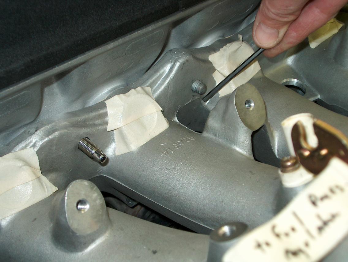
As the following photo shows, the head studs are marginally short. This is a particular problem at the top center location due to the fact that Skunk doesn't "surface" the holes along the top and there is a casting line at that location.
What I did was order studs from ARP (through Lightning Motorsports), part number AF2-000-12GB. I believe that these are the same studs that are included in the ARP intake manifold stud "kit". The only problem that I have with the kit is that it doesn't include lock washers, which I wanted to use. The photo shows one of the studs installed and you can see how it's longer.
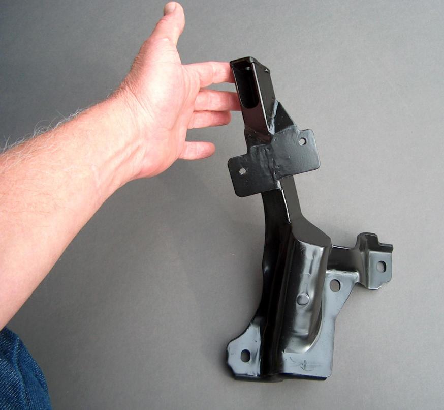
The support bracket;
The instructions that came with the manifold didn't make any recommendations as to if a stock (ITR?) bracket would work. It may be that they don't think that it's needed, but I'd question not running with one. I got a GSR bracket from a junk yard and modified it as shown to pick up the one threaded point on the under side of the manifold.
 "A"
"A"
 "B"
"B"
 "C"
"C"
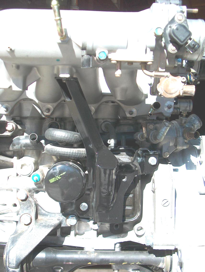 "D"
"D"
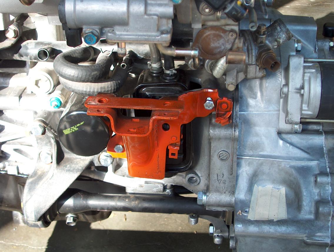
In photo "A", I mounted the stock GSR bracket on the block after painting it Chevy orange so that it shows up real clear in the photo. At that point, I used a cut-off saw (4" Mikita) to remove anything that didn't seem like it was needed. The photo doesn't show the mounting point on the underside of the manifold.
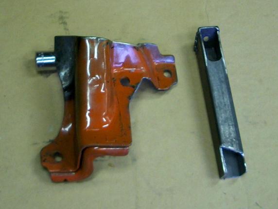
Photo "B" shows the piece of 1" square tube that I then made up to go from the manifold bolt to the bracket. On the left side of the bracket, you can notice that it's had it's paint burnt off. The reason is that I used a torch to heat up the bracket and bend it so that the tube would fit better. At the top of the tube, I welded a top plate with a hole in it. There is a slot in the side of the tube section that allows the bolt to be installed.
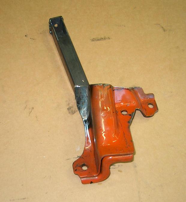
Photo "C" shows the bracket welded together.
In Photo "D", it's been painted black. Notice how the slotted hole at the top of the tube section allows the bolt to installed to the bottom of the manifold.
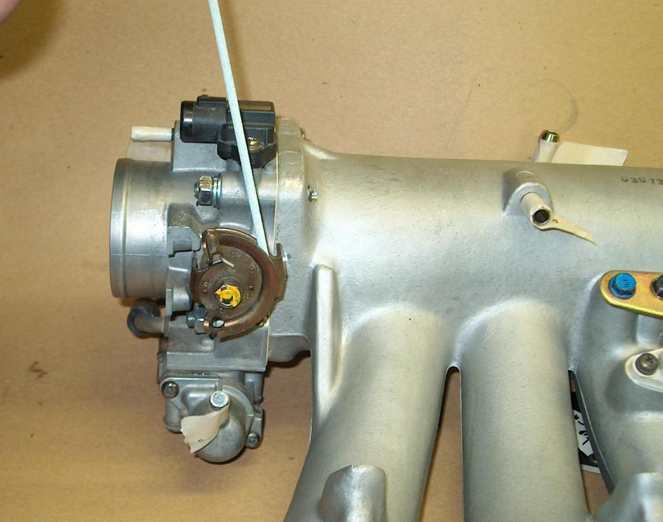
The throttle cable;
Due to the original GSR manifold placing the throttle body lower within the engine compartment, the hook up of the throttle cable is different than most other Honda models. As a result, the original mounting has the cable pull upward and not horizontal.
In the following photo, I've mounted the GSR throttle body on the Skunk 2 manifold and am holding a piece of brazing rod to show how the cable would "pull".
The next photo shows a (damaged) LS throttle body mounted on the Skunk2 manifold along with the ITR throttle cable bracket (16411-P73-000) attached. The piece of brazing rod shows how the cable would be positioned.
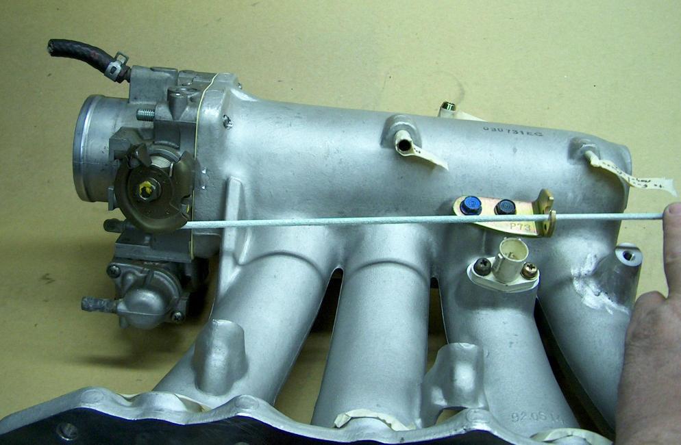
What I had to do was swap the "bell-crank" on the junk LS throttle body onto the GSR throttle body. It's just held on with one nut, but you have to make sure that you get the return spring on correctly when putting it back together.
(March 5, 2004; I ended up having to buy an ITR throttle cable to hook up the throttle. It's part number 17910ST7R01)
Another thing should be noted in the two prior photos; the water hook up at the base of the throttle body is different! Due to the fact that I was going to "re-plumb" a fair amount of stuff, I decided to keep the GSR style. It's real easy to just swap the housing (2 screws) if you want to. There may be a stock hose that fits if it's swapped and maybe somebody else could let me know.
Going through Hose "Heck";
Due to not having a complete car to look at, figuring out the routing of the hoses was a real pain. This is complicated by the fact that the stock GSR has the additional hoses and air reservoir to work the secondary track of the intake. I don't think this would be hard at all if just changing from one of the other Honda style manifolds. It's a little over-whelming when you are just looking at a ton of fittings that you know have to go somewhere.
What I did was to take some masking tape and when I figured out where a hose goes, mark the two fittings with a "letter", starting with "A". Once a fitting is marked, you know to not worry about it again and you can go on to the next. It is pretty much fashioned after a ITR set-up.
The PVC hose; The PVC line is hooked up to the air chamber mounted on the side of the block. In the stock GSR configuration, the angled PCV valve mounts directly on the box. In the Skunk 2 manifold, the valve is located near where the manifold bolts to the head, like in a ITR. It's for this reason that you should plan on buying the required ITR parts before starting (note; the instructions don't have all the correct part numbers listed).
 "A"
"A"
 "B"
"B"
 "C"
"C"
 "D"
"D"
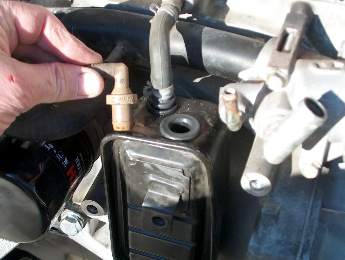
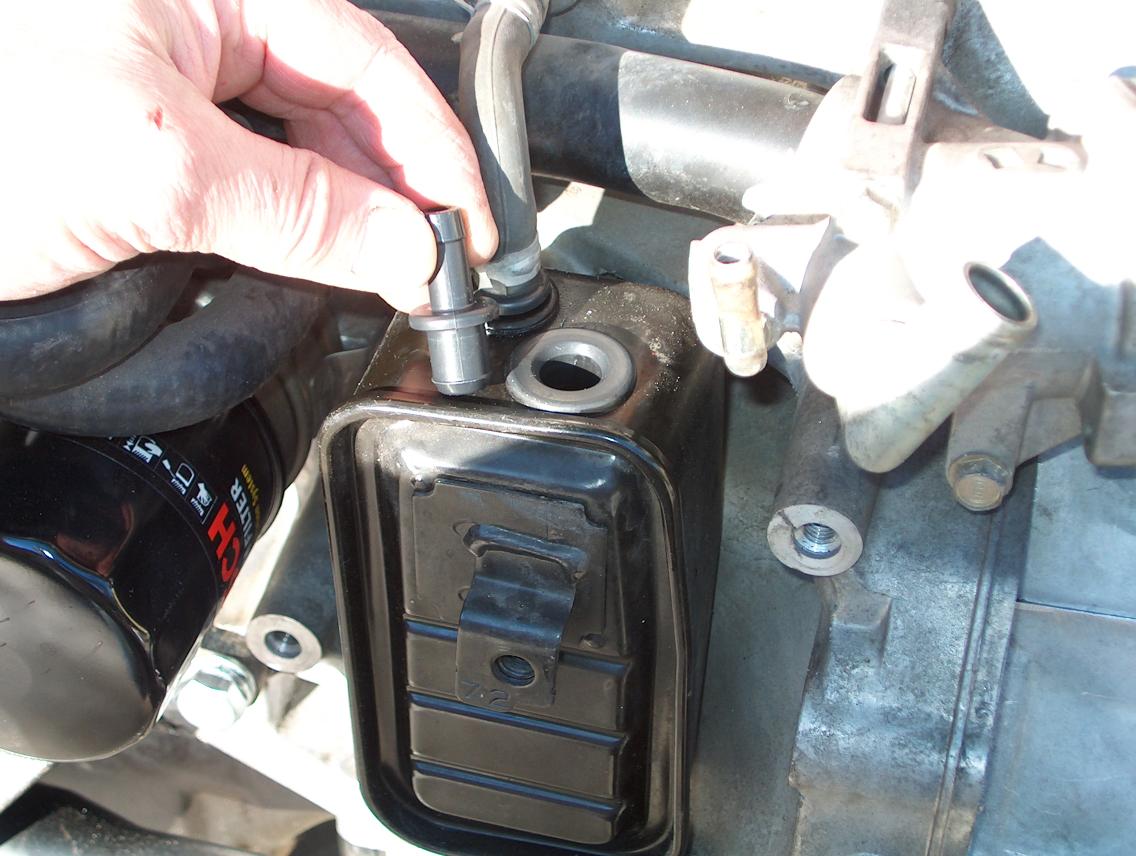
Photo "A" shows the air box and the PCV valve. In the stock GSR configuration, it would plug directly into the grommet in the box. You re-use the existing PCV valve, it's just re-located.
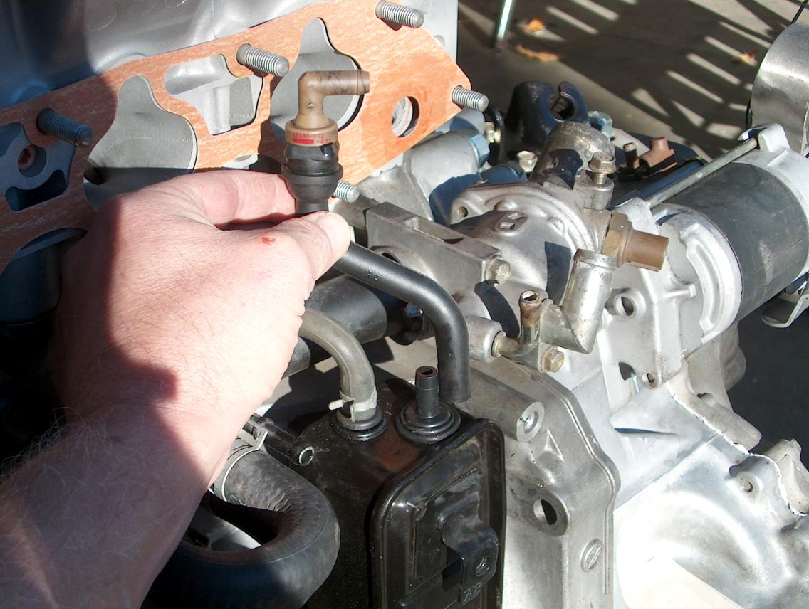
Photo "B" shows the ITR fitting that you will need (11854-PR3-000). What is hard to judge in the photos is that it's smaller in diameter than the PCV valve. I guess it would be possible to just buy a ITR box, but it's a lot easier (cheaper) than that! What I did is clean off the grommet with lacquer thinner and then use silicon sealer to glue the fitting in place. If you use black silicon, you can't even tell it's been done.
In Photo "C" I'm holding the ITR hose (11855-P30-000) and for reference, the PCV valve is placed in the top.
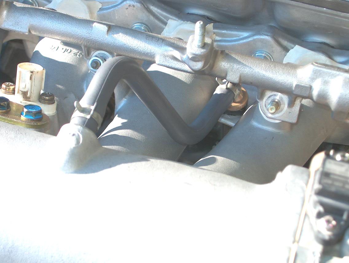
Photo "D" shows the upper PCV hose (11856-P30-000). You can also see the (brown) PCV valve in it's final location.
The EVAP valve; There isn't any provision to physically mount the EVAP valve and Skunk recommends that you just tie-wrap it to something. What I did is to make up a simple bracket that bolts to the end of the manifold. What may be a problem is if the master cylinder is in the way once the engine is installed.
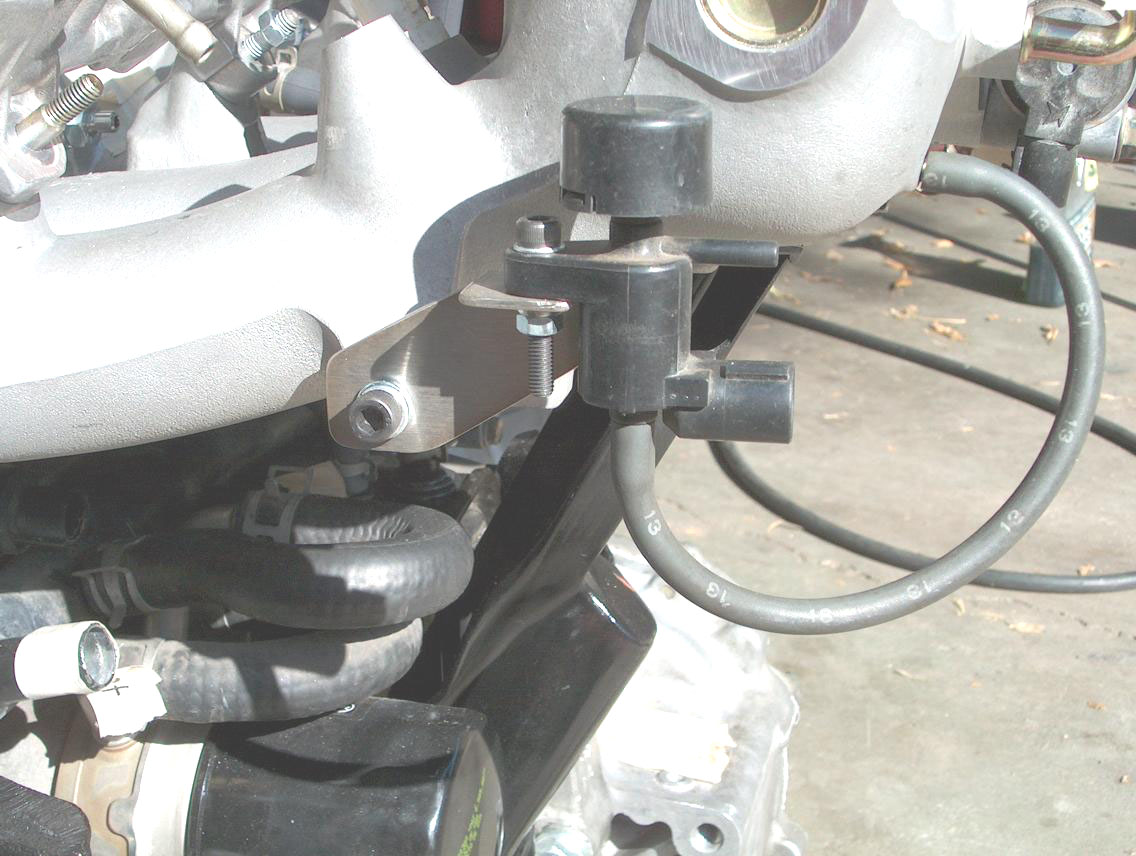
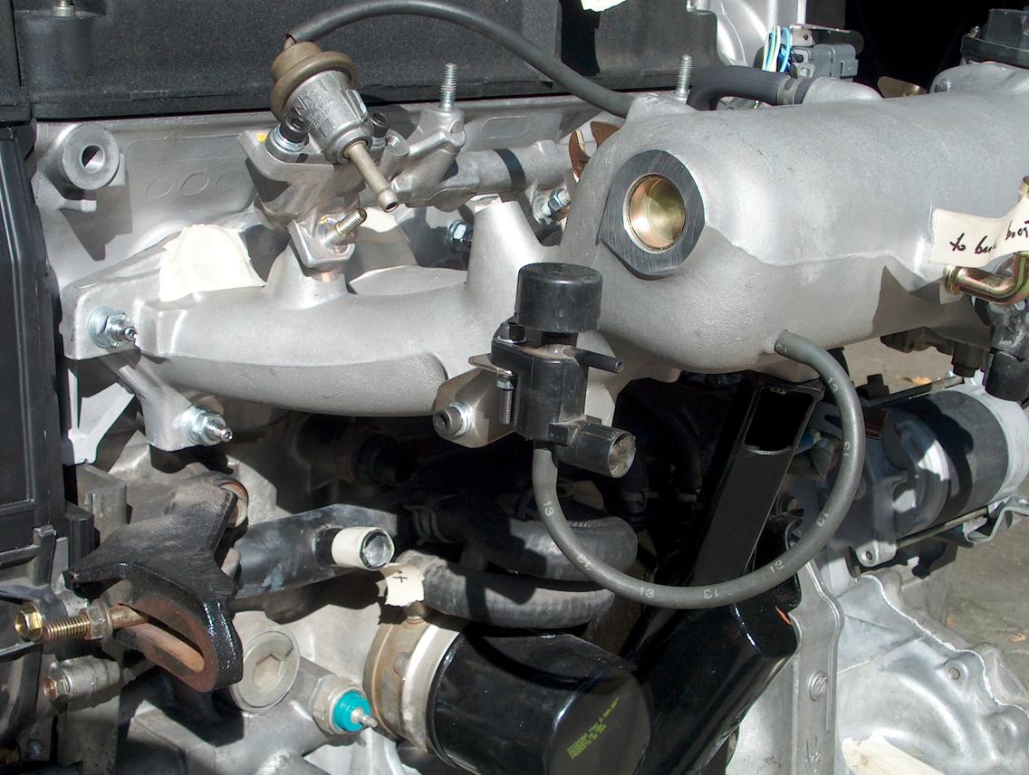
In the photo on the right, you can see where the fuel pressure regulator is plumbed to the intake manifold.
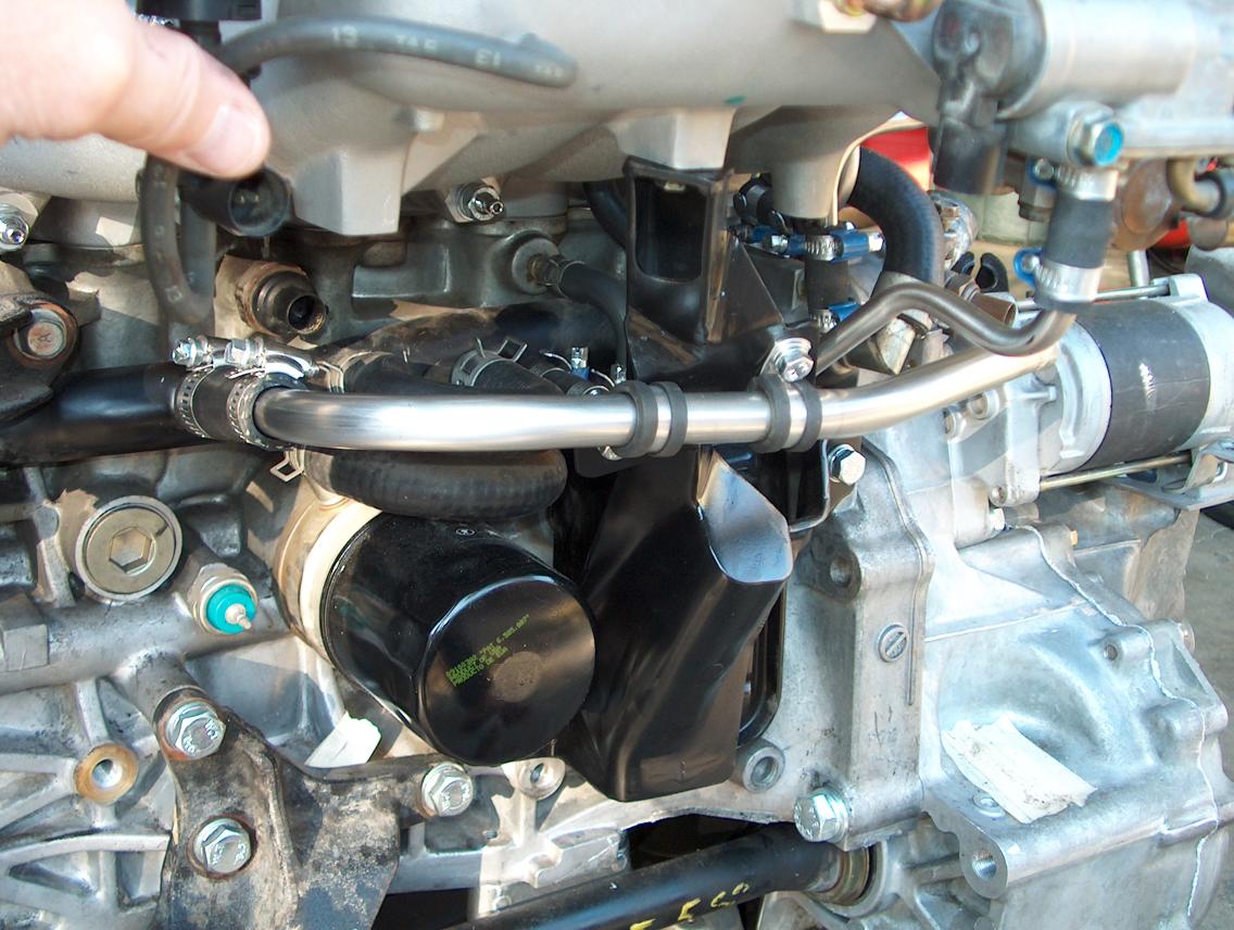
Water hoses to the intake;
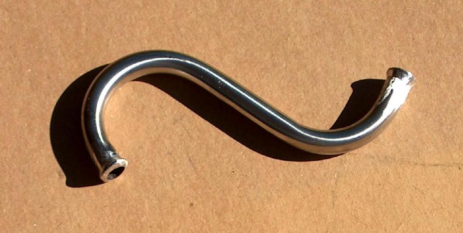
There were three hoses that I fabricated from 3/8" stainless hard line. When making up solid lines, you have to do something to keep the hose from coming off. What I do is take a thin piece of welding rod and bend it around the tube. Then I build up around it with solder. The solder is then filed down to the shape shown below.
These two photos show the line that goes from the IAC valve to the water cross-over tube.
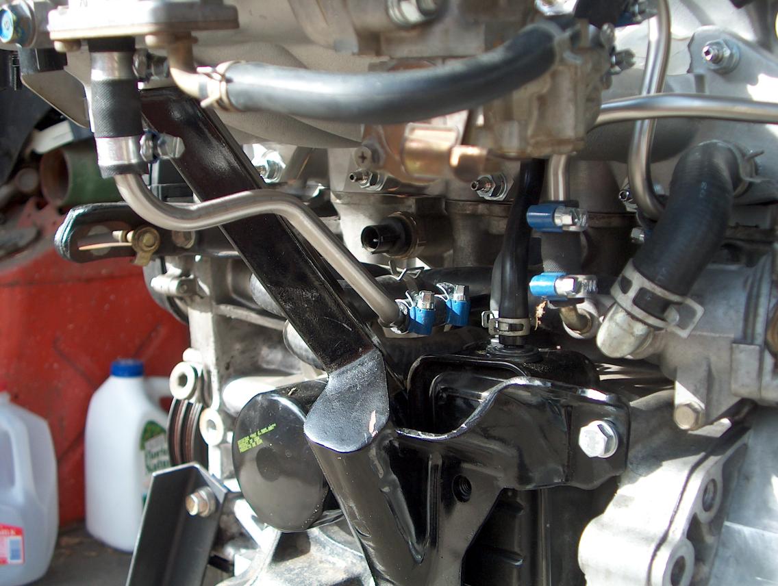
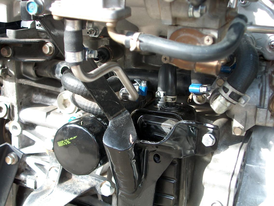
The next two photos show the two lines near the distributor.
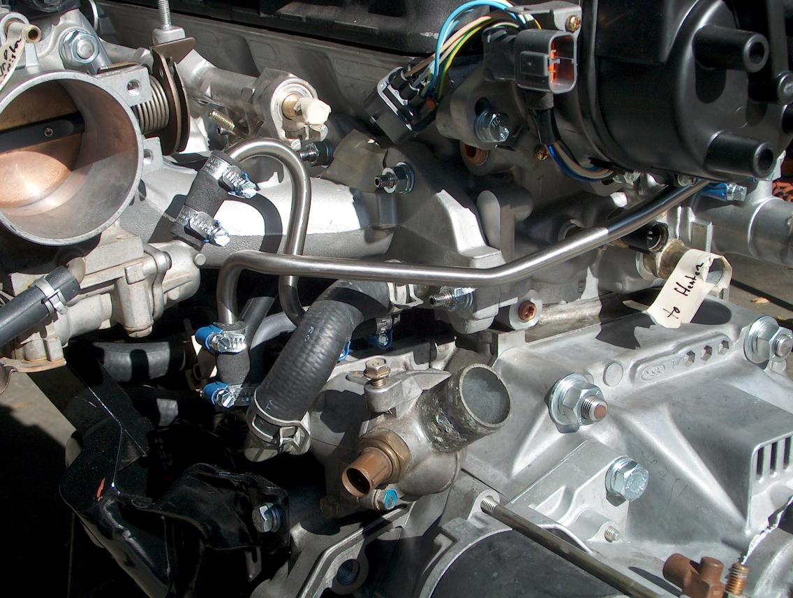
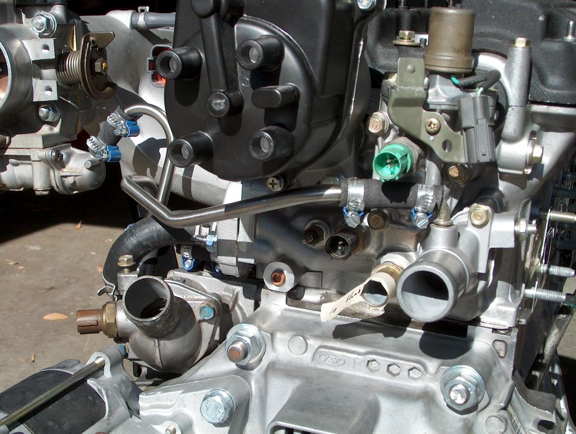
Now, I guess that there may be an ITR option to doing these hoses. If anybody knows, please let me know.
Injectors;
I picked up a set of used injectors for an OBD1 LS and felt that their history was rather "questionable" at best. Not to say that there was a concern about being stolen, but I didn't even know if they worked or not. I believe that the fuel rail was also from an LS, but I'm not really sure. All this was at the guidance given by a local speed shop. Due to my piecing the engine together (and don't have the car yet), there wasn't any way that I could just plug in the injectors and see if they would run.
What I did was to take the injectors to RC Engineering and talk to them. They told me that indeed, all of the OBD1 "B" series engines use the same injectors and that they would be adequate for the horsepower I wanted (just a mild GSR).
We took my injectors into the back and he did a quick test to see if they were OK. What we decided to do was to have them cleaned and "rebuilt". Keep in mind that it's only a limited rebuild.
It took only a couple days before they were returned by UPS.
What RC does is bead blast the outside to remove any rusting and then clear coat the body. From what I understand, they ultrasonically clean the inside. They provide a "data" sheet showing the before and after flow rates and comments on flow pattern. It cost about 100 dollars to have all four injectors done (including shipping). I'm impressed.
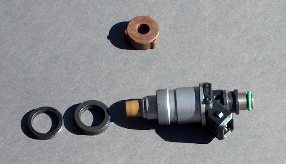
The photo above shows the injector as returned from RC Engineering. Also shown is the black "isolator" and black seal that I got from an Acura dealer. The brown item is an isolator that I thought I needed to go between the intake manifold and fuel rail (after looking through the factory GSR manual). Buy new seals!
I didn't need the brown isolator!! If I did use it (actually there are three of them), the fuel rail wouldn't have put any compression on the injector seals. Using the lower seal and black isolator, there was only a small amount of compression on the injector seals.
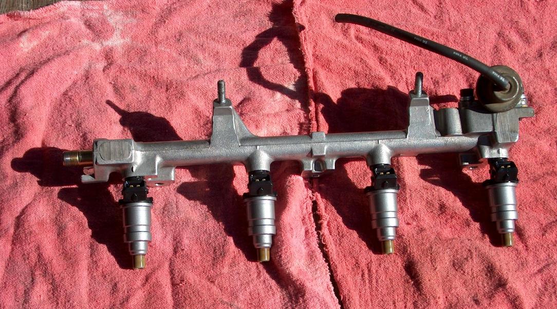
Here is the fuel rail with the injectors installed.
There is some issue with the three studs that hold on the fuel rail. On the GSR manifold, the two outside studs are longer and the shank is slightly larger in diameter. As a result, I had to drill out the outside mounting holes slightly larger. Another solution would be to use same size stud as what is in the center.
Put a small amount of oil on all of the injector seals before putting it on. You shouldn't have to force anything!
What should also be noted in the photo above is the location of the fuel pressure regulator! From what I understand, on some other versions the regulator isn't at the end and caused clearance problems with the intake temperature sensor.
More changes to the support bracket;
In making the up the hard line that would be the water line going to the heater, it became obvious that there would need some sort of support. The stock line bolts to the underside of the original GSR manifold. I made up the line using 5/8" stainless tube and figured out where I could support it. At that point, I welded on two "tabs" on the bracket that I'd built.
In this photo, you can see the two tabs and the holes drilled for the Adel clamps. What you can't see is that I welded nuts on the back sides so that putting it together would be easier.
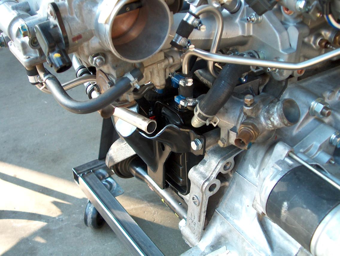
These two photos show the installed water line and how it's supported by the revised bracket.
return to my site's entry page
Wes Vann