Converting the wiring from OBD0 to OBD1
May 4, 2004
Just starting! Preliminary!!
To start off;
I don't recommend that everybody approach this in the manner that I did! The reason for what I did was a personal feeling about how the wiring should be routed and I'll get into that latter. (I'm old and over the years have formed all sorts of opinions that are different than most others out there doing Honda's)
This is not intended as a "how-to"!! What I'm going to try to do is show options and tips as to how it can be done different than most others.
I'm not an expert on all the different configurations that are possible when swapping Honda and Acura stuff. So, please don't e-mail me questions about any other configuration than what I did. My answer will just be a simple "I don't know". That leads to the next paragraph.
Buy the factory manuals for both the original car and the engine! Here is the link to Helmsinc.
Most photos will be "click-able" to view them larger. Use the back button to return here.
What would I recommend and why;
Even if you already know a lot about wiring, it's never easy and surely not quick!! You will make mistakes (I did).
Buy a "conversion harness" and get the engine fully running with no error codes (and VTEC working if you have it). By doing this, you rule out the possibility that a sensor is bad. At that point, if you don't like how the wiring is routed, re-work it circuit by circuit.
A conversion harness is a "interface" loom that plugs between the car's OBD0 loom and the new OBD1 ECU. Additional wires are also required for items not part of the original car.
Here are two sources of conversion harnesses; "jkobdconversion" and "locashracing". I have not done business with them and can't swear to the quality. When I last looked, the cost for an OBD0 to OBD1 conversion harness was $150. This is very reasonable when you think about the time saved and problems avoided.
What I did and why;
As I said in the beginning, I'm old and tend to get silly about certain things.
The B18C (or any B series engine for that matter) is a tight fit within the engine compartment of a 4G Civic. That means that if you need to replace the water pump, you may just have to pull the whole engine assembly. As a result, I wanted to be able to disconnect all the engine loom at one place (the passenger side fender) and pull the engine with all the connectors still attached to the sensors.
I wanted to clean up some of the wiring and route it differently. As an example, I wanted to get rid of the section that comes off of the drivers side fender. Of course, that means that it has to come out on the other side of the engine compartment, through the main loom gasket. Another example is that I didn't want the wiring to come out both sides of the long plastic holder near the injectors (it just isn't clean coming out both sides).
I didn't do what I recommended above and just bought a complete loom (engine and interior) from a 92 Civic. That was the source for almost all the parts that I would need. (it sure sounds easy and cheap)
When ever I do electrical work like this I always use "nude" butt splices, solder after crimping, and heat shrink tubing to cover it. All jokes aside, "nude" butt splices are ones that do not have the colored nylon sheathing on them. They have gotten hard to locate and I ended up ordering 200 of them from McMaster-Carr. (They come in packs of 100. Although it doesn't seem possible, I used more than 100!) Toward the bottom of this page, I'll cover soldering and stuff (to be added latter)
I found on the web a page written by Kurt W that outlined how to do all the interconnect at the ECU. Here is a link to the page; Kurt's OBD0-OBD1.
I made up several copies of the wiring diagrams out of the factory manuals. This is a good idea so that you can use a highlighting pen to cross out circuits you have completed.
So, at this point I was armed with diagrams, tons of wire with connectors and solder. I knew what I wanted to do, but just didn't know how to approach it! I spent several days in this condition. (blank & lost stare)
I finally decided to just jump in and potentially make trash of the original loom. I blindly followed Kurt's page and did all the changes under the dash (except for a few). Don't even think of doing all this "under-dash" work without removing the passenger seat! Even if you are only 16 years old, your back would kill you the next day.
There is something that I have to say about Kurt's page. In order to be nice, he includes two different numbering systems for the ECU pin-outs. The factory numbers all even number pins on one side, and the odd number pins on the other. Get used to the factory numbering and use a felt marker to scribble over the other numbering system! The potential to make mistakes is just too great when both numbering systems are there plus when you have to use the factory diagram, you will need to have their numbering system in your mind.
Another thing about Kurt's page was that the wire color call-outs for the OBD1 wires didn't always match what he had noted. The OBD0 coloring did match. This is not his fault and the only reason I'm saying anything is that I don't want anybody to get too weird or worried about it.
Cut and splice, cut and splice, cut and splice. That got me a good percentage of the under-dash work done.
Now here is where I went off the deep end (in regards to how everybody else does this stuff)! I pretty much completely rebuilt and customized the engine loom and it's connections to the car.
I wanted to use the "grey" connectors that are common on OBD1 looms and this included the inter-connect sockets mounted at the passenger side fender. Also at that point, I kept the rectangular socket that has that hideous plastic cover (It's for high amperage connections). If you count up all the wires that have to go through this location, (and that includes the ones relocated from the drivers side loom) you will soon realize that there are just not enough pins available.
The grey sockets come in a 10 pin and 14 pin version. So, I converted both sockets on the fender to 14 pin and also mounted a 14 pin socket (I could have used a 10 pin one) on the firewall. The firewall socket has it's own engine loom and it goes to things like the MAP and throttle position sensors mounted on the intake manifold.
insert photo here
At that point, it was a matter of laying out and routing the wiring as I wanted, using the wires taken from the 92 loom.
By the way, among the other things to buy, pick up a ton of tie-wraps. I picked up a sack of 100. Use them to hold things together as you work. Cut them off and add a new one as a new wire is put in place. Don't be cheap.
Some wiring just fell in place. As an example, the distributor wiring to the grey connector was pretty much used as is and didn't require modifying. Of course, that only gets you to the grey connector and a splice has to be made between it and the loom that comes through the firewall. One by one, I used an OHM meter and "buzzing" from the ECU connection found the needed wire at the old "white" (OBD0) connector. It was cut free and spliced to the correct location on a grey connector.
Some wires need to be added and they were all pulled through the firewall grommet and connected as needed. Some of the wires have to be "shielded", with a ground attached to the shielding.
At this point I have to add a warning in to regards to using the factory manual's wiring diagram. When the manuals were written, the assumption was that an individual has brought his unmodified car into the dealer for repair. As such, section 11 covers all the wiring in regards to the fuel injection. Section 23 covers all the other wiring items, in separate sections like "radiator fan", "water temperature gauge", etc. This leads to the fact that there isn't a complete wiring diagram of the engine loom in the standard factory manual.
The reason this is important to know is that if you are going to do major work on the engine loom, you have to go to different sections of the manual to figure out all the wiring! As an example, there are three different water temperature sensors on the engine and only one is shown in the ECU wiring diagram (It doesn't even clearly call out which one it is!).
It all makes sense, but you have to dig through the manual to find all the information that you will end up needing.
Once everything was connected, I had a friend come over and we re-buzzed all the circuits, highlighting them off on a copy of the wiring diagram. There are some wires that can't be easily checked and are pretty much on blind faith (well, based on what the two manuals lead you to believe is true). An example is the wiring that goes to the water temperature gauge on the dash. I'd have to pull the dash apart to verify that it goes to the correct place (the gauge works after re-wiring, so it is ok).
I pulled the loom, added that plastic sleeve, wrapped it with electrical tape, and added "mounts" (strain relieve mounts) where possible. Here are before and after photos. (notice the tie-wraps all over the place, they were removed as the loom was wrapped.
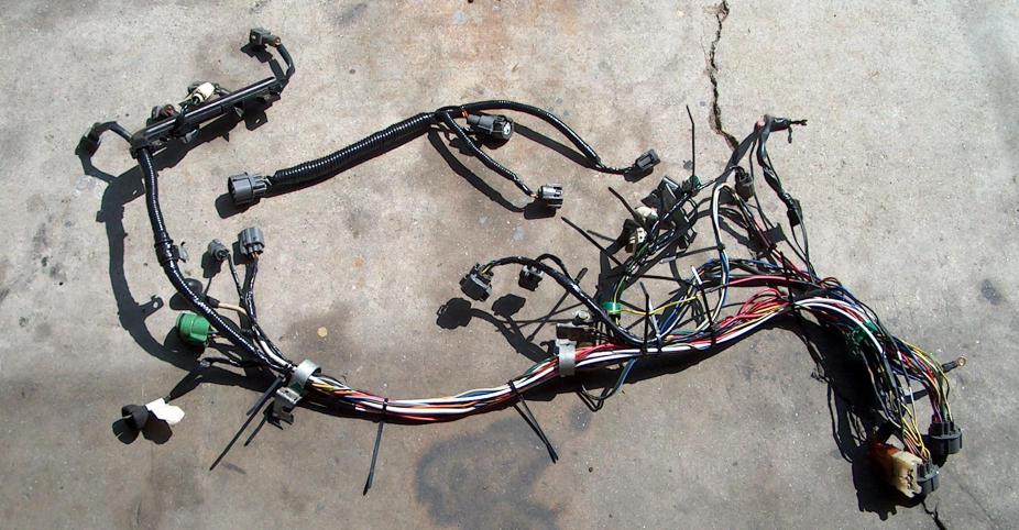
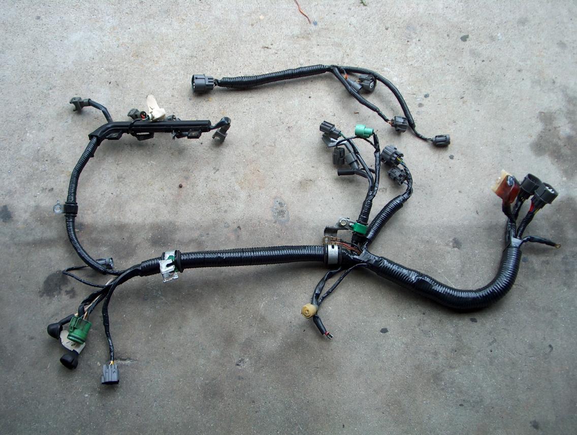
(click on the photo to see it larger)
That little loom at the top of the photo is the "firewall" loom and it goes to the sensors that are on the intake manifold.
Once everything was hooked up, I tried to start the car. It would gleefully crank over, but not start! I had spark, fuel, and the ECU didn't throw any codes. After a lot of "hair pulling out" (and I'm pretty much bald), the guys at Lightning Motorsport (buy parts from them!!) recommended that I check the MAP and Throttle Position Sensor circuits. I buzzed out those circuits again and they seemed ok. I then used the "trouble shooting" flow charts in the factory manual to check the voltages at both sensors. What happened was that two of the three wires at the MAP sensor were hooked up backwards (my error). I swapped them and the engine started right up.
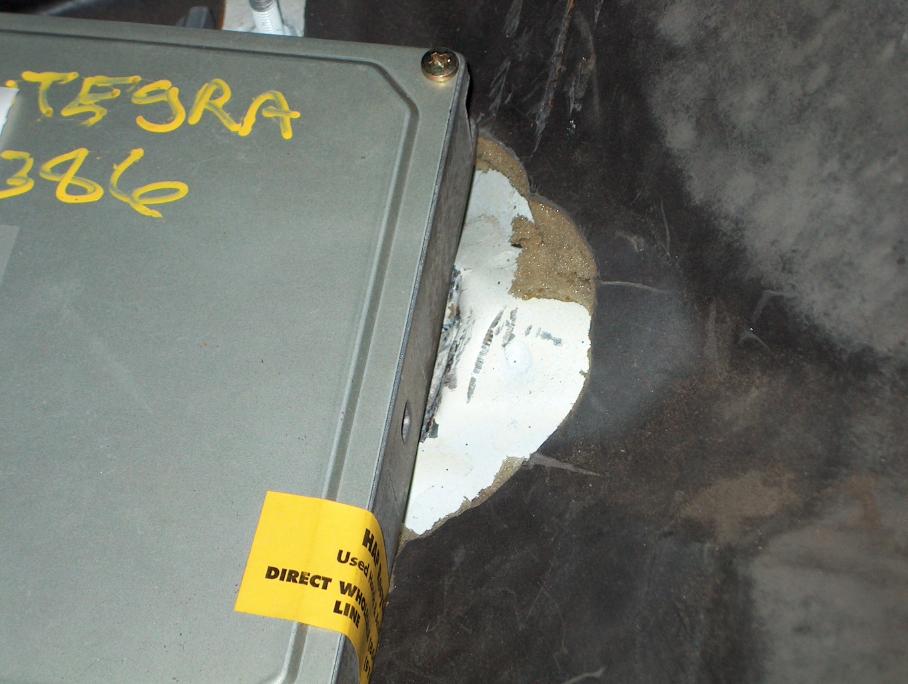
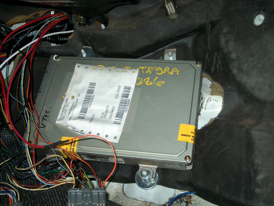
Mounting and covering the ECU;
It's possible to mount the new P72A1 OBD1 ECU in the stock location and still have the floor board (firewall) cover fit. It's a "strange" fit, but it works. I'm not sure if all OBD1 ECU's are the same physical size!
First off, I cut out any sections of the insulating material that would get in the way. Then I took a short handle sledge hammer and beat down the "bump" in the floor board at the right side of where the ECU would mount.
At this point, it became obvious that the upper right mounting tab on the ECU wouldn't work and so I cut it off. Use a hand hacksaw to do this and be real careful that none of the metal gets inside the ECU box. The reason that I recommend that you use a hand hacksaw is that you want to be careful about static electricity! Without the box having the inputs connected, it would be possible to damage it with just a small static electric spark!
Now the box fit pretty much flat on the floor board. The problem is that the ECU mounting tabs are not on the bottom edge. So, I used a stack of fender washers under the tabs. You don't want the washers to lift the ECU off the floor board, but to just prevent the tabs from being bent down. The stud that is at the upper right should have normal washers stacked so that the total height is the same as if there was still a tab on the ECU (the cover plate will bear directly on this stack of washers).
With the ECU in place, you will notice that it can move up and down along the firewall. It has to be free to move around at this point.
Now this is real hard to explain, but the shape of the cover plate will force the ECU to be "centered", up and down between the mounting studs.
With the cover plate installed, I was able to get a nut on all four studs and tightened them down. There isn't any extra stud length, but just enough.
Make sure that you don't pinch any wires!
Making connections;
this is where I will cover soldering and connectors
Closing comments;
So, after all that I only had one wiring error (two swapped pins), and a wiring job that looks like the factory did it. It's clean and routed as I wanted. It's easy to dis-connect if I have to remove the engine to service it. The smog Referee shouldn't have any complaints!
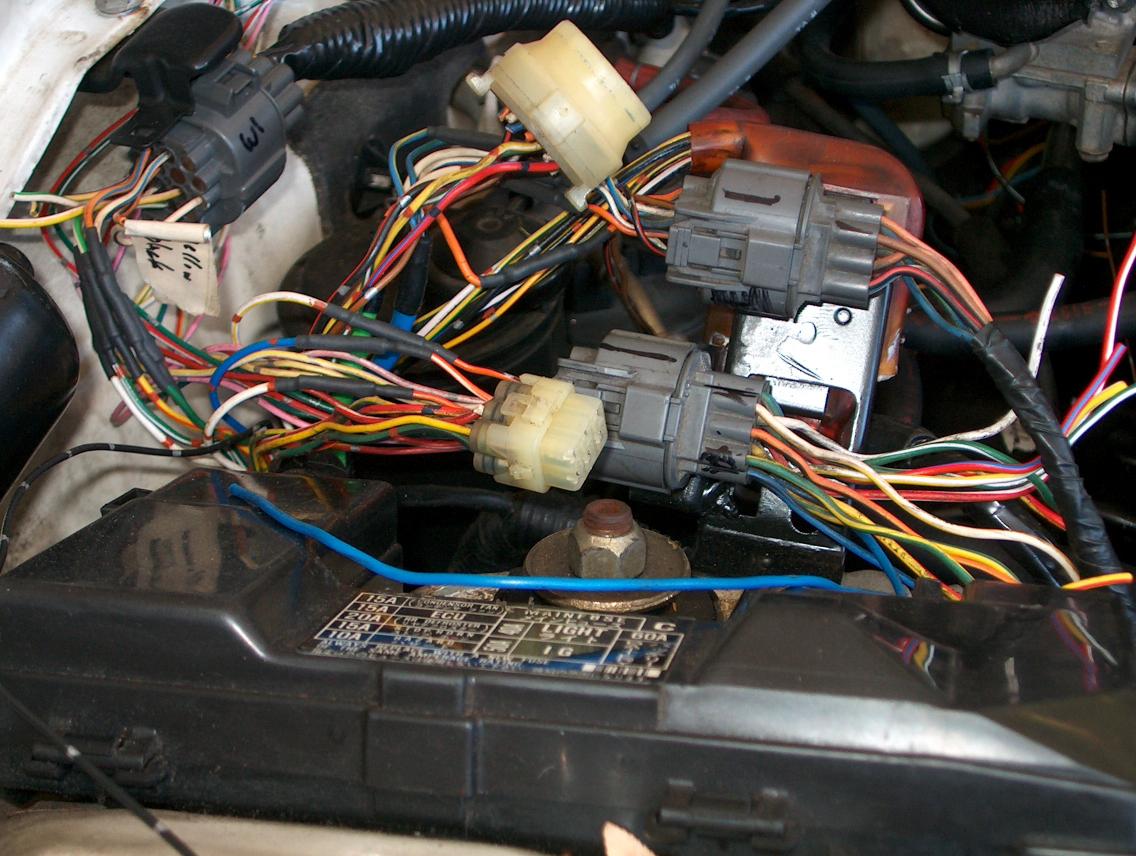
Here is a photo showing loom installed and all wrapped (at the passenger side fender)
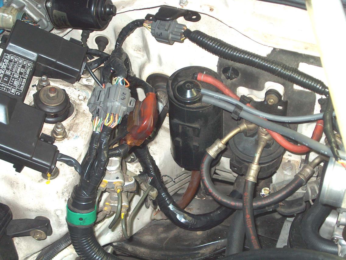
This next photo shows the drivers side.
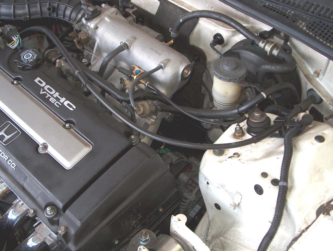
There are two things that should be noted in this photo. There are no electrical connections made from the loom that runs along the drivers fender. The other thing isn't too clear (unless you click on the photo to see the larger version) is that the injector wiring (and IAT sensor) wiring only exits the plastic loom holder and dodges under the intake manifold.
return to my site's entry page
Wes Vann