My Rust Diary
June 8, 2009; replacing the front floor pan and misc. other items;
It's been quite some time since I've added anything to this section. I've been busy doing other stuff on the car.
When I first got my car, the prior owner had already purchased the rear floor pan section (from Restoration Design) and he gave it to me with the car.
The installation of the rear section is covered in the prior pages.
There was enough rust in the remaining section to warrant replacing it also.
I purchased the pan section directly from Restoration Design.
My installation was complicated by the chassis jig the car was sitting on, which got in the way a lot. If you were doing this on a rotiserie, it wouldn't be hard at all.
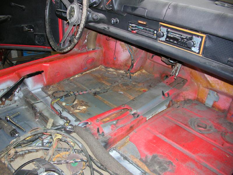
The front floor pan;
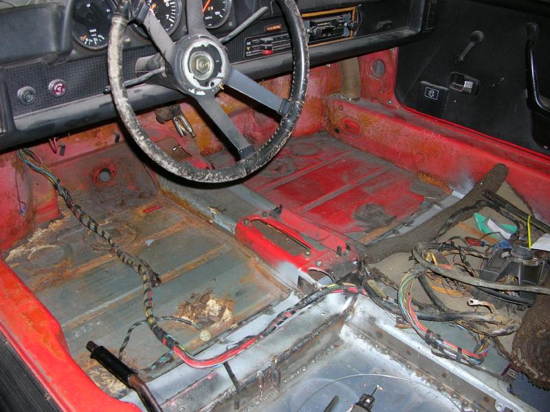
Here are photos of the floor section prior to cutting it out;
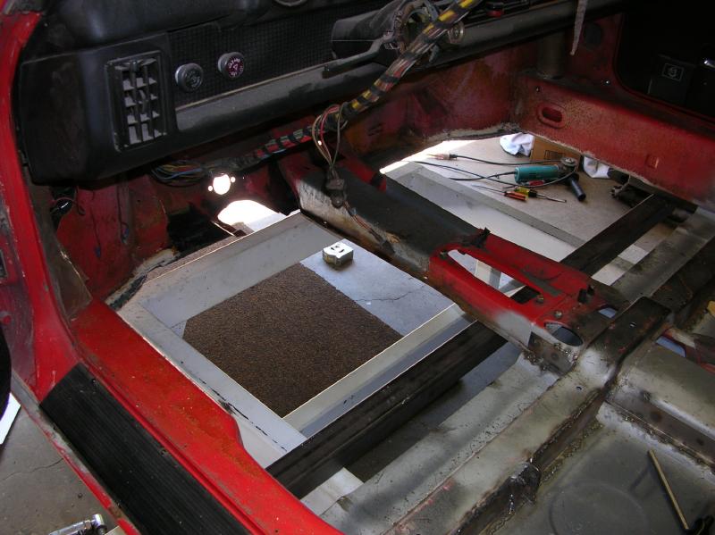
And here it is, after cutting out a major section;
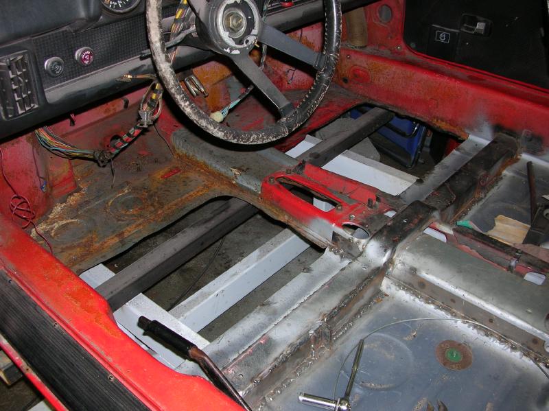
Now notice all the framework under the car, that is the chassis jig.
Another thing, that isn't clear in the photo, is that there are two studs that go through the floor to attach the pedal assembly. In addition there are two holes, with nuts on the under side, that are what the gas pedal is attached to. This is all part of a stiffener on the under side of the pan.
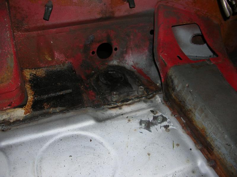
This is a photo of the pedal assembly stiffener, from under the car.
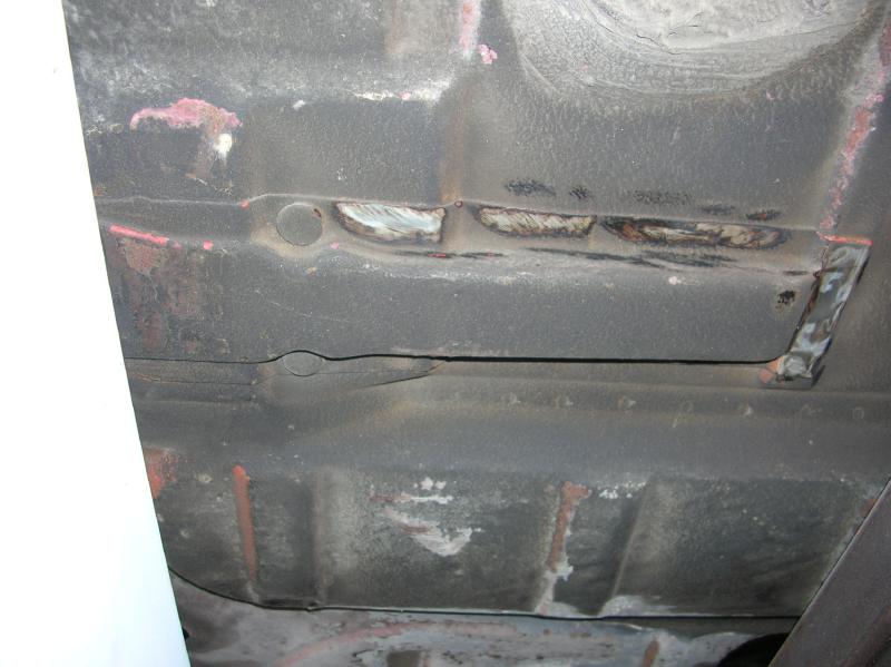
The two round items are the heads for the studs that hold the pedal assembly. What can't be seen from this view is one of the weld-nuts that hold the gas pedal. The other weld nut is hidden within the bracket.
This bracket is not available as a reproduction!!!
I couldn't just drill out the spot welds due to the chassis jig being in the way.
The "cut-line" I envisioned for the new pan went right through the bracket.
The solution I came up with was to just cut out the whole section;
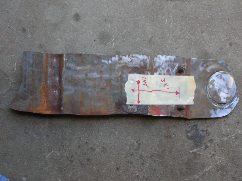
The photo above, on the left, shows the removed section viewed from the top. Notice the two studs. They are for the pedal assembly. To the left of them are the holes for the weld-nuts that hold the gas pedal (partially hidden by the tape.
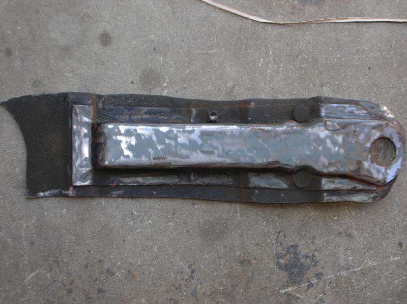
In the photo above, on the right, you see the bracket as if viewed from under the car. You can clearly see the heads for the studs and also one of the weld-nuts.
Now this is out of sequence, but is best shown here;
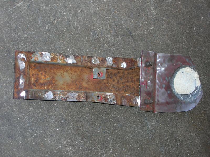
After welding in the front pan section, I removed the old floor section from the bracket. The following two photos show the bracket prior to welding it back onto the car. Notice that the "hidden" weld nut was attached to a small bracket within the assembly.
And after treating the inside with a rust converter.
Starting off, I didn't use the full length of the pan. I cut off about 2 inches from the front edge. The reason was that I wanted to avoid the brackets that are on the kick-board, about half way along the curved section of the wheel well.
The next two photos show the desired cut-line marked on the existing floor (from under the car).
Here is a photo showing the total removed area.
And with the pan in place.
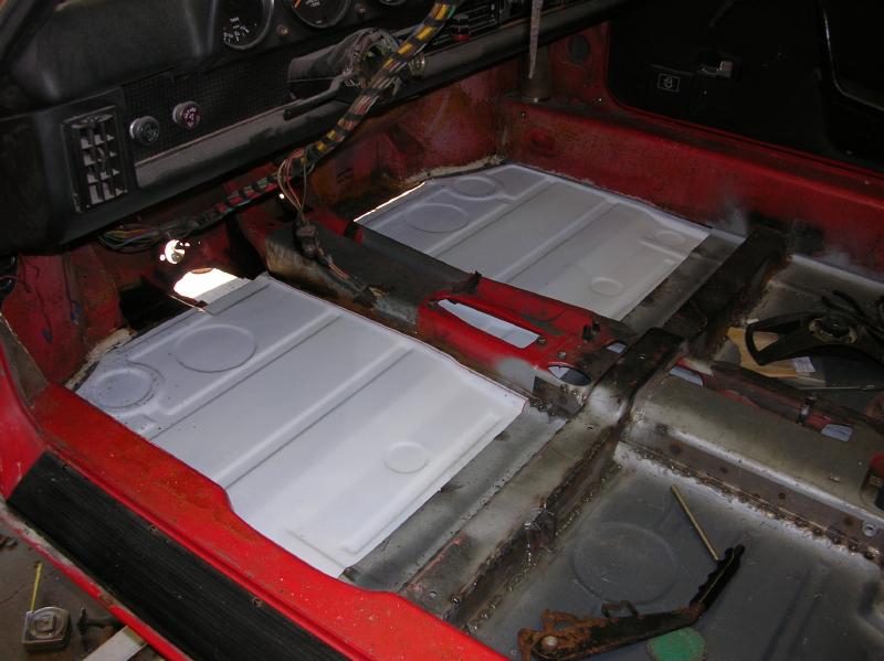
At this point, I could figure out the amount of "over-lap" between the front pan and the already installed rear pan. There was about 1 1/2" of overlap that had to be cut off.
Also note that opening where I cut out the brake pedal stiffener bracket.
Then it was a matter of welding away.
I then welded the brake pedal stiffener back in.
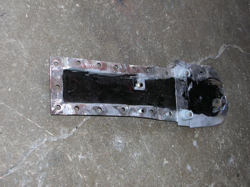
This photo shows the floor pan prior to welding in the pedal stiffener. Note the holes for the gas pedal bolts.
Here is a photo showing the floor after welding that bracket (and floor section) in place.
There are a couple things that should be noted.
The first is that I installed a bunch of washers and nuts over the studs to protect them while grinding and welding.
The other is that prior to welding the stiffener in place, I drilled holes for the gas pedal bolts. I used the bolts (shown in the photo above) to help align the bracket.
The Seat Hinge Brackets;
When I got my car, there were no seat hinge brackets! The previous owner had cut out that section.
I got re-productions from Bill at Restoration Design. He doesn't show or list them on his web site and you have to ask about them. What you get is the metal base piece that is welded to the floor pan with the hinge already welded to it. It also has the nut-serts installed.
Placement of the brackets isn't an issue as long as you have the seat base removed from the seat.
I bolted up everything as shown in the lower photo, pushed it as far forward as possible and tack welded the brackets in place (one of them sits in a raised section of the floor pan). I then made sure that the release lever worked correctly, before doing any extensive welding.
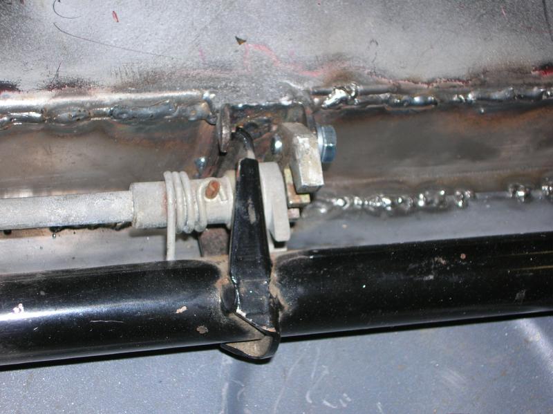
The following photo shows the finished installation.
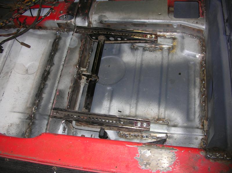
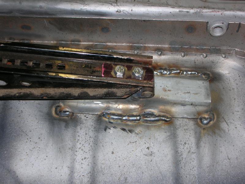
In the next photo, you can see that I made up a washer plate for the two attachment bolts. I don't really know what the factory did, but I wanted to make sure that the bolt heads couldn't pull through the slotted holes in the seat bracket.
The final photo (for this segment) shows the release bracket, just for reference.
The Rear Jacking Point Brackets;
When you remove the rear floor pan section, you also have to remove the rear jacking point brackets. These are the triangle shaped brackets that run along the bottom of the frame rail (in the engine compartment) and onto the lower section of the rear firewall / cross-member.
Once again, I got them from Bill at Restoration Design.
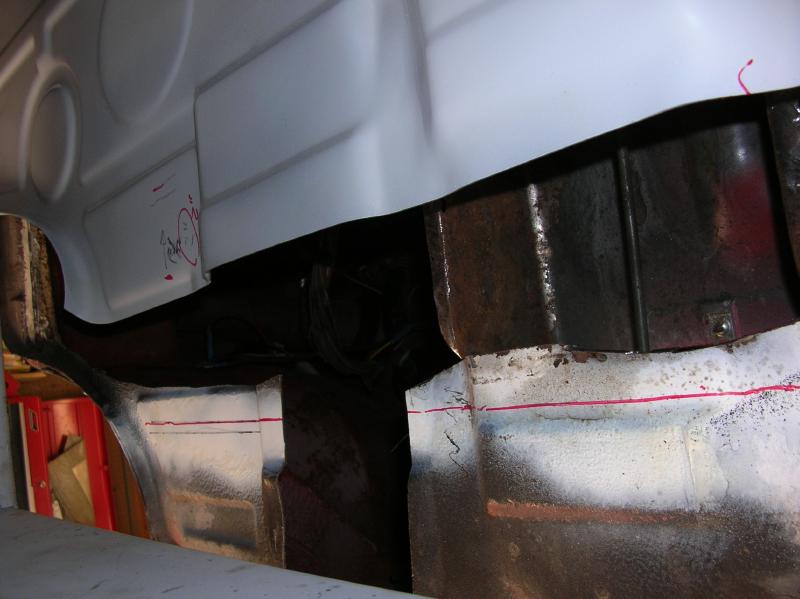
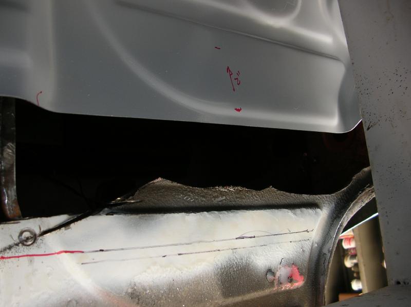
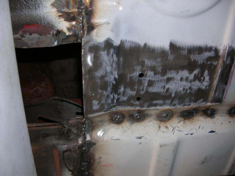
Prior to installing the passenger side bracket, I added the over-lay shown in the following photo. There was surface rust in this area and I wanted to supplement what was there.
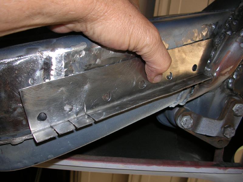
(There is still some additional welding, but it's outside of the area covered by the jacking point bracket. I can get to this area better once the car is off of the chassis jig)
Notice in the photo above the curved, indented area on the frame rail. I used this to "index" the placement of the brackets.
Here is a photo of one of the brackets, ready to be welded in place.
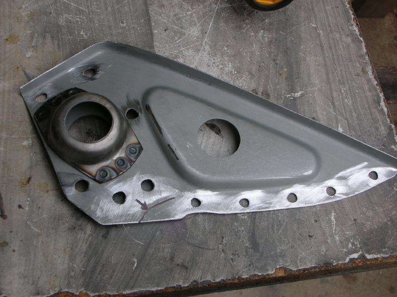
They come from Restoration Design already welded together, as shown.
Notice the curved line I marked on the bracket. It's an indented area and is what I used to line up the bracket with the indent on the frame rail. Some minor notching and trimming was required.
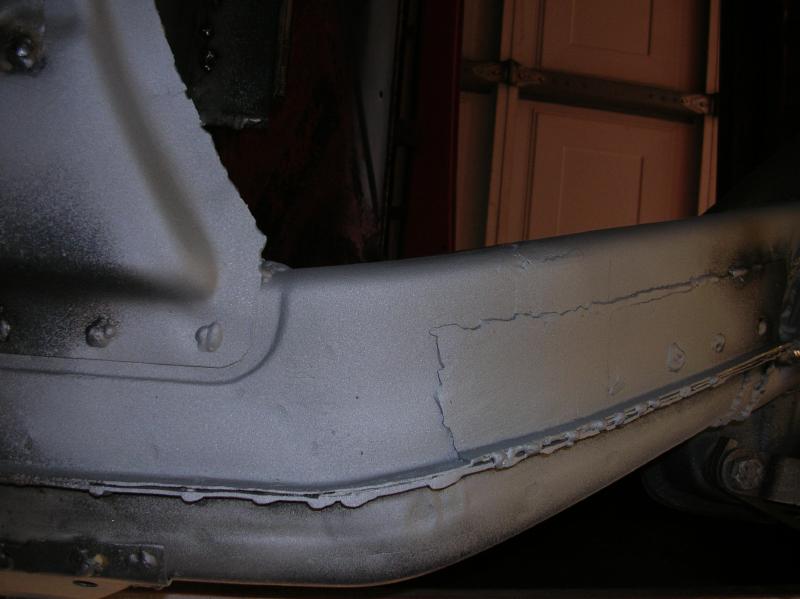
The final two photos show the two sides welded in place.
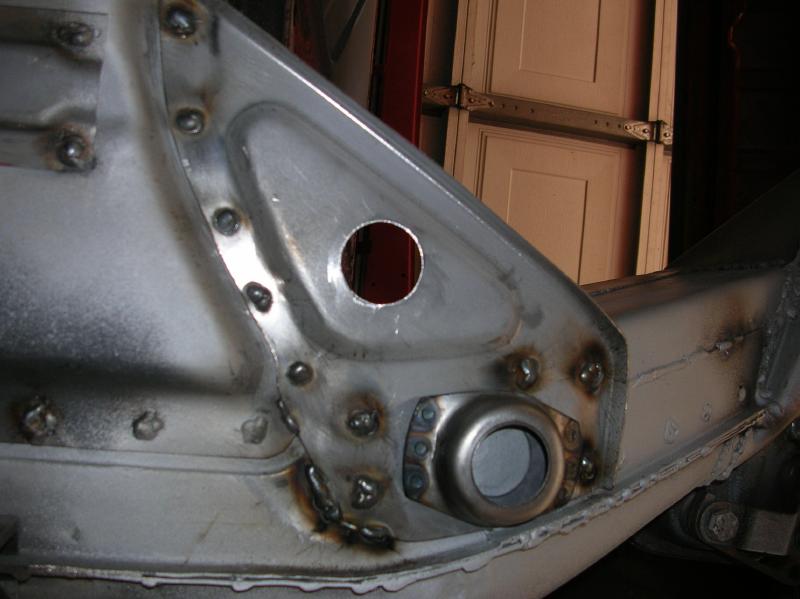
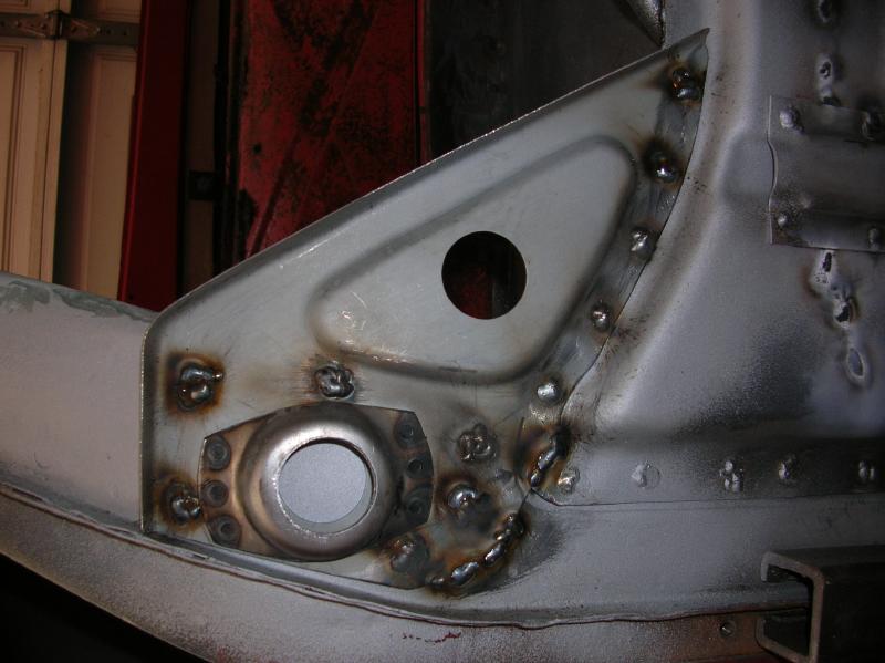
Final comments;
That pretty much completes my rust diary.
There are a couple little brackets that still have to be fabricated and welded in place. Plus, I need to get the Engman stiffener kit and weld it in.
The only reason for keeping the car on the chassis jig is so that I can anchor it well while doing the welding on the Engman kit. Other than that, I could put the car on it's wheels. (Damn, that will be a happy day!!!)
There is a whole bunch of "finish" welding that has to be done. A lot of it has been put off due to the chassis jig being in the way.
It's been a lot of F'ing work, that most people will never know happened. If you expect to get respect from your non-car friends for what was done, you have wasted your time.
So, that's it for the Rust Diary!
go to the prior "rust diary" page
return to my "rust diary" entry page
return to my site's entry page
Wes Vann